Chapter 11
Communication & Navigation

Area Navigation (RNAV)
Area navigation (RNAV) is a general term used to describe the navigation from point A to point B without direct over flight of navigational aids, such as VOR stations or ADF non-directional beacons. It includes VORTAC and VOR/DME based systems, as well as systems of RNAV based around LORAN, GPS, INS, and the FMS of transport category aircraft. However, until recently, the term RNAV was most commonly used to describe the area navigation or the process of direct flight from pointA to point B using VORTAC and VOR/DME based references which are discussed in this section.
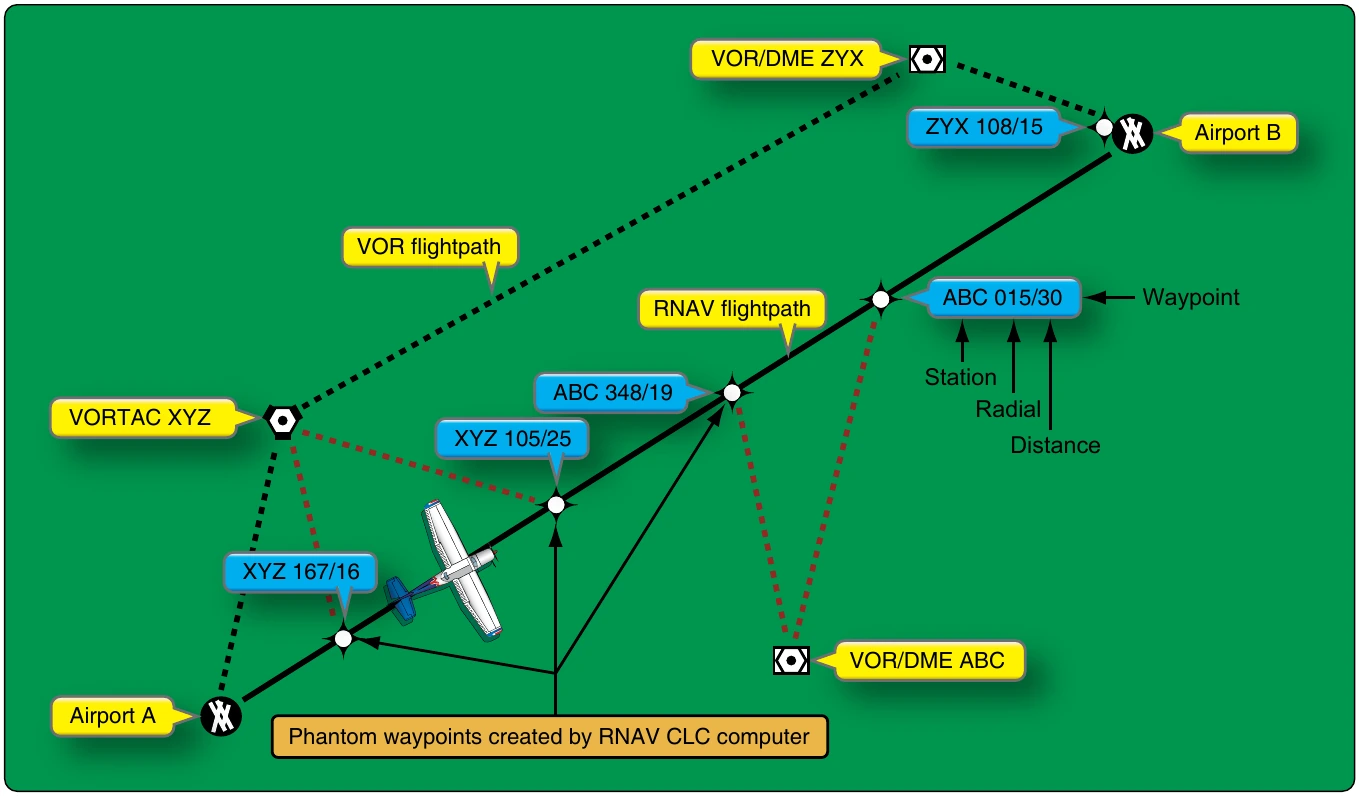
All RNAV systems make use of waypoints. A waypoint is a designated geographical location or point used for route definition or progress-reporting purposes. It can be defined or described by using latitude/longitude grid coordinates or, in the case of VOR based RNAV, described as a point on a VOR radial followed by that point’s distance from the VOR
VOR station on the 200° radial).
Figure 11-123 illustrates an RNAV route of flight from airport A to airport B. The VOR/DME and VORTAC stations shown are used to create phantom waypoints that are overflown rather than the actual stations. This allows a more direct route to be taken. The phantom waypoints are entered into the RNAV course-line computer (CLC) as a radial and distance number pair. The computer creates the waypoints and causes the aircraft’s CDI to operate as though they are actual VOR stations. A mode switch allows the choice between standard VOR navigation and RNAV.
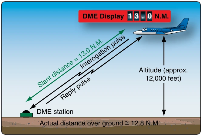
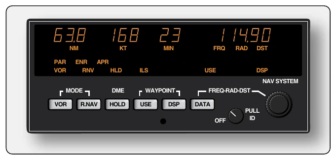
VOR based RNAV uses the VOR receiver, antenna, and VOR display equipment, such as the CDI. The computer in the RNAV unit uses basic geometry and trigonometry calculations to produce heading, speed, and time readouts for each waypoint. VOR stations need to be within line-of sight and operational range from the aircraft for RNAV use. [Figure 11-124]
RNAV has increased in flexibility with the development of GPS. Integration of GPS data into a planned VOR RNAV flight plan is possible as is GPS route planning without the use of any VOR stations.
Radar Beacon Transponder
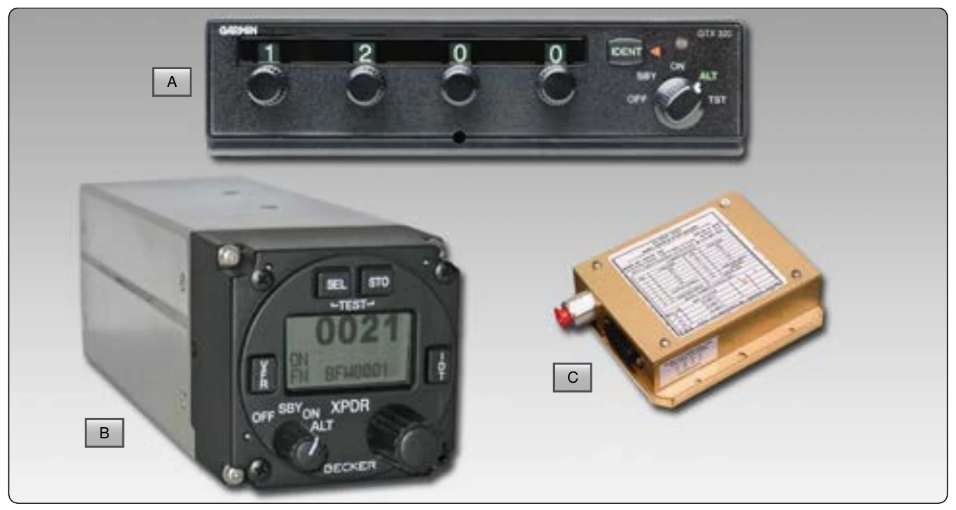
A radar beacon transponder, or simply, a transponder, provides positive identification and location of an aircraft on the radar screens of ATC. For each aircraft equipped with an altitude encoder, the transponder also provides the pressure altitude of the aircraft to be displayed adjacent to the on-screen blip that represents the aircraft. [Figure 11-125]
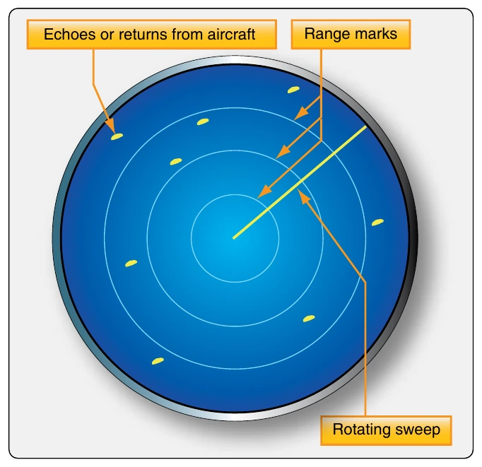
Radar capabilities at airports vary. Generally, two types of radar are used by air traffic control (ATC). The primary radar transmits directional UHF or SHF radio waves sequentially in all directions. When the radio waves encounter an aircraft, part of those waves reflect back to a ground antenna. Calculations are made in a receiver to determine the direction and distance of the aircraft from the transmitter. A blip or target representing the aircraft is displayed on a radar screen also known as a plan position indicator (PPI). The azimuth direction and scaled distance from the tower are presented giving controllers a two dimensional fix on the aircraft. [Figure 11-126] A secondary surveillance radar (SSR) is used by ATC to verify the aircraft’s position and to add the third dimension of altitude to its location. SSD radar transmits coded pulse trains that are received by the transponder on board the aircraft. Mode 3/A pulses, as they are known, aid in confirming the location of the aircraft. When verbal communication is established with ATC, a pilot is instructed to select one of 4,096 discrete codes on the transponder. These are digital octal codes. The ground station transmits a pulse of energy at 1030 MHz and the transponder transmits a reply with the assigned code attached at 1090 MHz. This confirms the aircraft’s location typically by altering its target symbol on the radar screen. As the screen may be filled with many confirmed aircraft, ATC can also ask the pilot to ident. By pressing the IDENT button on the transponder, it transmits in such a way that the aircraft’s target symbol is highlighted on the PPI to be distinguishable.