Chapter 11
Communication & Navigation
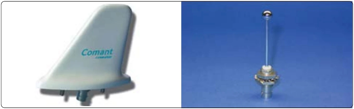
To gain altitude clarification, the transponder control must be placed in the ALT or Mode C position. The signal transmitted back to ATC in response to pulse interrogation is then modified with a code that places the pressure altitude of the aircraft next to the target symbol on the radar screen. The transponder gets the pressure altitude of the aircraft from an altitude encoder that is electrically connected to the transponder. Typical aircraft transponder antennas are illustrated in Figure 11-127.
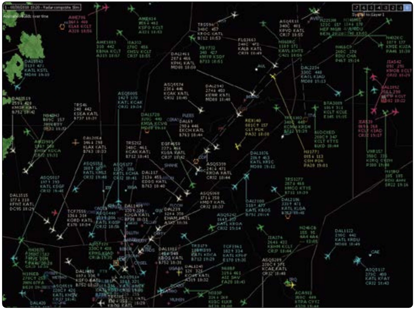
The ATC/aircraft transponder system described is known as Air Traffic Control Radar Beacon System (ATCRBS). To increase safety, Mode S altitude response has been developed. With Mode S, each aircraft is pre-assigned a unique identity code that displays along with its pressure altitude on ATC radar when the transponder responds to SSR interrogation. Since no other aircraft respond with this code, the chance of two pilots selecting the same response code on the transponder is eliminated. A modern flight data processor computer (FDP) assigns the beacon code and searches flight plan data for useful information to be displayed on screen next to the target in a data block for each aircraft. [Figure 11-128]
Mode S is sometimes referred to as mode select. It is a data packet protocol that is also used in onboard collision avoidance systems. When used by ATC, Mode S interrogates one aircraft at a time. Transponder workload is reduced by not having to respond to all interrogations in an airspace.
Additionally, location information is more accurate with Mode S. A single reply in which the phase of the transponder reply is used to calculate position, called monopulse, is sufficient to locate the aircraft. Mode S also contains capacity for a wider variety of information exchange that is untapped potential for the future. At the same time, compatibility with older radar and transponder technology has been maintained.
Transponder Tests & Inspections
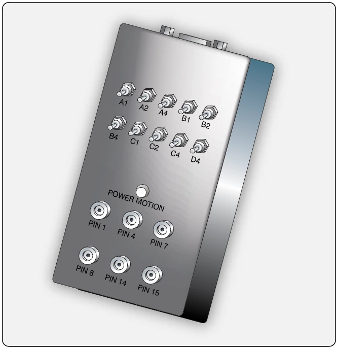
Title 14 of the Code of Federal Regulations (CFR) part 91, section 91.413 states that all transponders on aircraft flown into controlled airspace are required to be inspected and tested in accordance with 14 CFR part 43, Appendix F, every 24 calendar months. Installation or maintenance that may introduce a transponder error is also cause for inspection and test in accordance with Appendix F. Only an appropriately rated repair station, the aircraft manufacturer (if it installed transponder), and holders of a continuous airworthy program are approved to conduct the procedures. As with many radio-electronic devices, test equipment exists to test airworthy operation of a transponder. [Figure 11-129]
Operating a transponder in a hangar or on the ramp does not immunize it from interrogation and reply. Transmission of certain codes reserved for emergencies or military activity must be avoided. The procedure to select a code during ground operation is to do so with the transponder in the OFF or STANDBY mode to avoid inadvertent transmission. Code 0000 is reserved for military use and is a transmittable code. Code 7500 is used in a hijack situation and 7600 and 7700 are also reserved for emergency use. Even the inadvertent transmission of code 1200 reserved for VFR flight not under ATC direction could result in evasion action. All signals received from a radar beacon transponder are taken seriously by ATC.
Altitude Encoders
Altitude encoders convert the aircraft’s pressure altitude into a code sent by the transponder to ATC. Increments of 100 feet are usually reported. Encoders have varied over the years. Some are built into the altimeter instrument used in the instrument panel and connected by wires to the transponder. Others are mounted out of sight on an avionics rack or similar out of the way place. These are known as blind encoders. On transport category aircraft, the altitude encoder may be a large black box with a static line connection to an internal aneroid. Modern general aviation encoders are smaller and more lightweight, but still often feature an internal aneroid and static line connection. Some encoders use microtransistors and are completely solid-state including the pressure sensing device from which the altitude is derived. No static port connection is required. Data exchange with GPS and other systems is becoming common. [Figure 11-130]
When a transponder selector is set on ALT, the digital pulse message sent in response to the secondary surveillance radar interrogation becomes the digital representation of the pressure altitude of the aircraft. There are 1280 altitude codes, one for each 100 feet of altitude between 1200 feet mean sea level (MSL) and 126,700 feet MSL. Each altitude increment is assigned a code. While these would be 1280 of the same codes used for location and IDENT, the Mode C (or S) interrogation deactivates the 4096 location codes and causes the encoder to become active. The correct altitude code is sent to the transponder that replies to the interrogation. The SSR receiver recognized this as a response to a Mode C (or S) interrogation and interprets the code as altitude code.
Collision Avoidance Systems
The ever increasing volume of air traffic has caused a corresponding increase in concern over collision avoidance. Ground-based radar, traffic control, and visual vigilance are no longer adequate in today’s increasingly crowded skies. Onboard collision avoidance equipment, long a staple in larger aircraft, is now common in general aviation aircraft.
New applications of electronic technology combined with lower costs make this possible.
Traffic Collision Avoidance Systems (TCAS)
Traffic collision avoidance systems (TCAS) are transponder based air-to-air traffic monitoring and alerting systems. There are two classes of TCAS. TCAS I was developed to accommodate the general aviation community and regional airlines. This system identifies traffic in a 35–40 mile range of the aircraft and issues Traffic Advisories (TA) to assist pilots in visual acquisition of intruder aircraft. TCAS I is mandated on aircraft with 10 to 30 seats.
TCAS II is a more sophisticated system. It is required internationally in aircraft with more than 30 seats or weighing more than 15,000 kg. TCAS II provides the information of TCAS I, but also analyzes the projected flightpath of approaching aircraft. If a collision or near miss is imminent, the TCAS II computer issues a Resolution Advisory (RA). This is an aural command to the pilot to take a specific evasive action (i.e., DESCEND). The computer is programmed such that the pilot in the encroaching aircraft receives an RA for evasive action in the opposite direction (if it is TCAS II equipped). [Figure 11-131]
The transponder of an aircraft with TCAS is able to interrogate the transponders of other aircraft nearby using SSR technology (Mode C and Mode S). This is done with a 1030 MHz signal. Interrogated aircraft transponders reply with an encoded 1090 MHz signal that allows the TCAS computer to display the position and altitude of each aircraft. Should the aircraft come within the horizontal or vertical distances shown in Figure 11-131, an audible TA is announced. The pilot must decide whether to take action and what action to take. TCAS II equipped aircraft use continuous reply information to analyze the speed and trajectory of target aircraft in close proximity. If a collision is calculated to be imminent, an RA is issued.