
Chapter 13
Aircraft Landing Gear Systems
Vane-Type
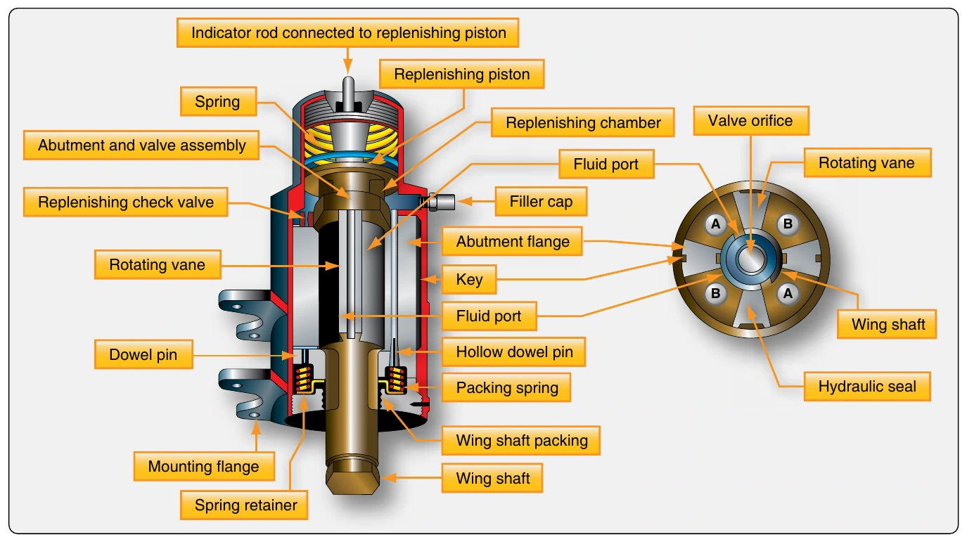
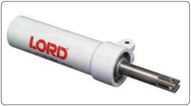
A vane-type shimmy damper is sometime used.[Figure 13-56] It uses fluid chambers created by the vanes separated by a valve orifice in a center shaft. As the nose gear tries to oscillate, vanes rotate to change the size of internal chambers filled with fluid. The chamber size can only change as fast as the fluid can be forced through the orifice. Thus, the gear oscillation is dissipated by the rate of fluid flow. An internal spring-loaded replenishing reservoir keeps pressurized fluid in the working chambers and thermal compensation of the orifice size is included. As with the piston type shimmy damper, the vane-type damper should be inspected for leaks and kept serviced. A fluid level indicator protrudes from the reservoir end of the unit.
Non-Hydraulic Shimmy Damper
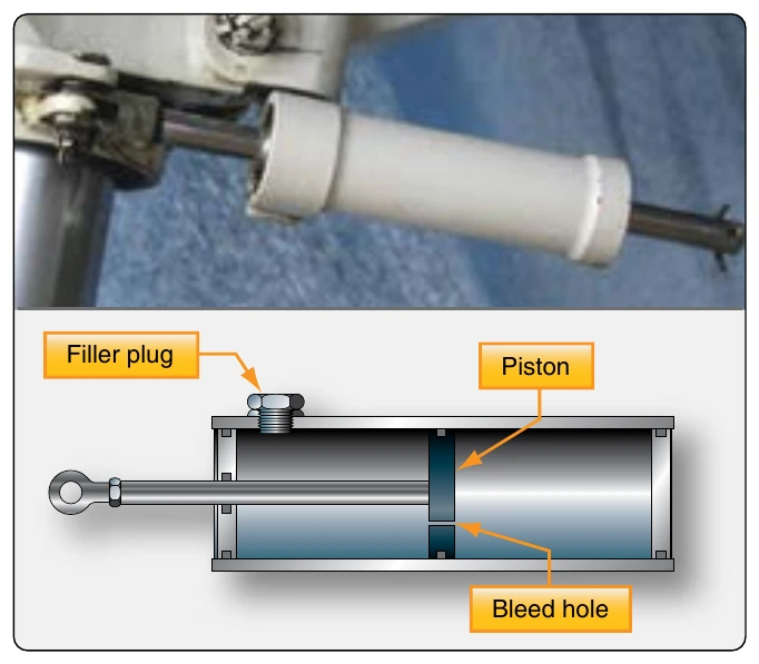
Non-hydraulic shimmy dampers are currently certified for many aircraft. They look and fit similar to piston-type shimmy dampers but contain no fluid inside. In place of the metal piston, a rubber piston presses out against the inner diameter of the damper housing when the shimmy motion is received through the shaft. The rubber piston rides on a very thin film of grease and the rubbing action between the piston and the housing provides the damping.
This is known as surface-effect damping. The materials used to construct this type of shimmy damper provide a long service life without the need to ever add fluid to the unit. [Figure 13-57]
Aircraft Wheels
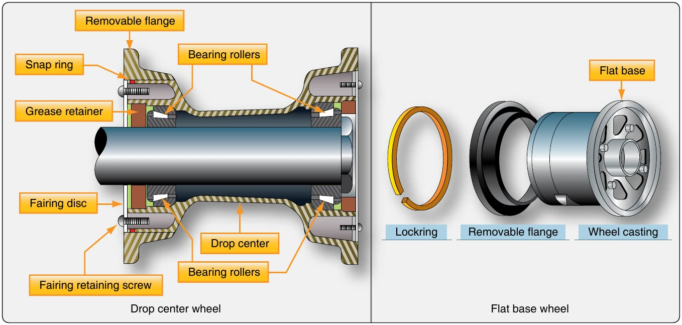
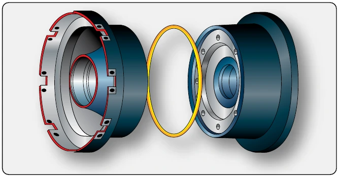
Aircraft wheels are an important component of a landing gear system. With tires mounted upon them, they support the entire weight of the aircraft during taxi, takeoff, and landing. The typical aircraft wheel is lightweight, strong, and made from aluminum alloy. Some magnesium alloy wheels also exist. Early aircraft wheels were of single piece construction, much the same as the modern automobile wheel. As aircraft tires were improved for the purpose they serve, they were made stiffer to better absorb the forces of landing without blowing out or separating from the rim. Stretching such a tire over a single piece wheel rim was not possible. A two-piece wheel was developed. Early two-piece aircraft wheels were essentially one-piece wheels with a removable rim to allow mounting access for the tire. These are still found on older aircraft. [Figure 13-58] Later, wheels with two nearly symmetrical halves were developed. Nearly all modern aircraft wheels are of this two-piece construction. [Figures 13-59 and 13-60]
Wheel Construction
The typical modern two-piece aircraft wheel is cast or forged from aluminum or magnesium alloy. The halves are bolted together and contain a groove at the mating surface for an o-ring, which seals the rim since most modern aircraft utilize tubeless tires. The bead seat area of a wheel is where the tire actually contacts the wheel. It is the critical area that accepts the significant tensile loads from the tire during landing. To strengthen this area during manufacturing, the bead seat area is typically rolled to prestress it with a compressive stress load.
Inboard Wheel Half
Wheel halves are not identical. The primary reason for this is that the inboard wheel half must have a means for accepting and driving the rotor(s) of the aircraft brakes that are mounted on both main wheels. Tangs on the rotor are fitted into steel reinforced keyways on many wheels. Other wheels have steel keys bolted to the inner wheel halves. These are made to fit slots in the perimeter of the brake rotor. Some small aircraft wheels have provisions for bolting the brake rotor to the inner wheel half. Regardless, the inner wheel half is distinguishable from the outer wheel half by its brake mounting feature. [Figure 13-61]
Both wheel halves contain a bearing cavity formed into the center that accepts the polished steel bearing cup, tapered roller bearing, and grease retainer of a typical wheel bearing set-up. A groove may also be machined to accept a retaining clip to hold the bearing assembly in place when the wheel assembly is removed. The wheel bearings are a very important part of the wheel assembly and are discussed in a later section of this chapter.
The inner wheel half of a wheel used on a high-performance aircraft is likely to have one or more thermal plugs. [Figure 13-62] During heavy braking, temperatures can become so great that tire temperature and pressure rise to a level resulting in explosion of the wheel and tire assembly. The thermal plug core is filled with a low melting point alloy. Before tire and wheel temperatures reach the point of explosion, the core melts and deflates the tire. The tire must be removed from service, and the wheel must be inspected in accordance with the wheel manufacturer’s instructions before return to service if a thermal plug melts. Adjacent wheel assemblies should also be inspected for signs of damage. A heat shield is commonly installed under the inserts designed to engage the brake rotor to assist in protecting the wheel and tire assembly from overheating.
An overinflation safety plug may also be installed in the inner wheel half. This is designed to rupture and release all of the air in the tire should it be over inflated. The fill valve is also often installed in the inner wheel half with the stem extending through holes in the outer wheel half to permit access for inflation and deflation.