
Chapter 13
Aircraft Landing Gear Systems
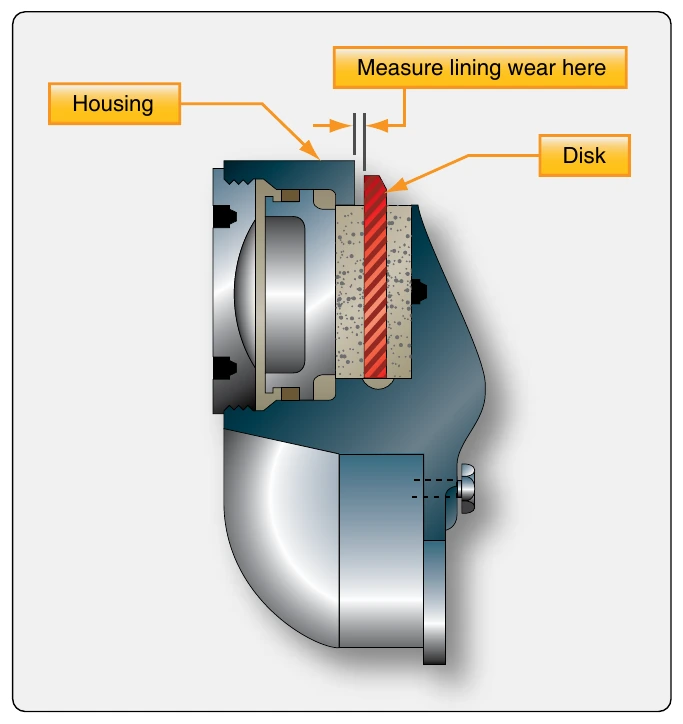
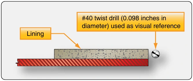
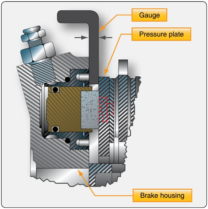
Multiple disc brakes typically are checked for lining wear by applying the brakes and measuring the distance between the back of the pressure plate and the brake housing. [Figure 13-117] Regardless of the method particular to each brake, regular monitoring and measurement of brake wear ensures linings are replaced as they become unserviceable. Linings worn beyond limits usually require the brake assembly to be removed for replacement.
Air in the Brake System
The presence of air in the brake system fluid causes the brake pedal to feel spongy. The air can be removed by bleeding to restore firm brake pedal feel. Brake systems must be bled according to manufacturers’ instructions. The method used is matched to the type of brake system. Brakes are bled by one of two methods: top down, gravity bleeding or bottom up pressure bleeding. Brakes are bled when the pedals feel spongy or whenever the brake system has been opened.
Bleeding Master Cylinder Brake Systems
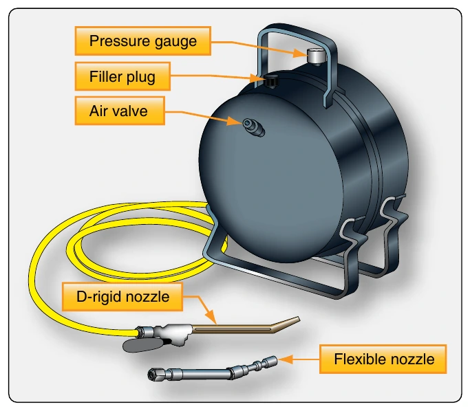
Brake systems with master cylinders may be bled by gravity or pressure bleeding methods. Follow the instructions in the aircraft maintenance manual. To pressure bleed a brake system from the bottom up, a pressure pot is used. [Figure 13-118] This is a portable tank that contains a supply of brake fluid under pressure. When dispersing fluid from the tank, pure air-free fluid is forced from near the bottom of the tank by the air pressure above it. The outlet hose that attaches the bleed port on the brake assembly contains a shut-off valve. Note that a similar source of pure, pressurized fluid can be substituted for a pressure tank, such as a hand-pump type unit found in some hangars.
The typical pressure bleed is accomplished as illustrated in
the bleed port on the brake assembly. A clear hose is attached to the vent port on the aircraft brake fluid reservoir or on the master cylinder if it incorporates the reservoir. The other end of this hose is placed in a collection container with a supply of clean brake fluid covering the end of the hose. The brake assembly bleed port is opened. The valve on the pressure tank hose is then opened allowing pure, air-free fluid to enter the brake system. Fluid containing trapped air is expelled through the hose attached to the vent port of the reservoir. The clear hose is monitored for air bubbles. When they cease to exist, the bleed port and pressure tank shutoff are closed, and the pressure tank hose is removed. The hose at the reservoir is also removed. Fluid quantity may need to be adjusted to assure the reservoir is not over filled. Note that it is absolutely necessary that the proper fluid be used to service any brake system including when bleeding air from the brake lines.
Brakes with master cylinders may also be gravity bled from the top down. This is a process similar to that used on automobiles. [Figure 13-120] Additional fluid is supplied to the aircraft brake reservoir so that the quantity does not exhaust while bleeding, which would cause the reintroduction of more air into the system. A clear hose is connected to the bleed port on the brake assembly. The other end is submersed in clean fluid in a container large enough to capture fluid expelled during the bleeding process. Depress the brake pedal and open the brake assembly bleed port. The piston in the master cylinder travels all the way to the end of the cylinder forcing air fluid mixture out of the bleed hose and into the container. With the pedal still depressed, close the bleed port. Pump the brake pedal to introduce more fluid from the reservoir ahead of the piston in the master cylinder. Hold the pedal down and open the bleed port on the brake assembly. More fluid and air is expelled through the hose into the container. Repeat this process until the fluid exiting the brake through the hose no longer contains any air. Tighten the bleed port fitting and ensure the reservoir is filled to the proper level.
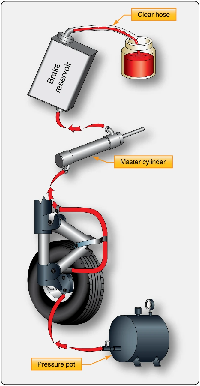
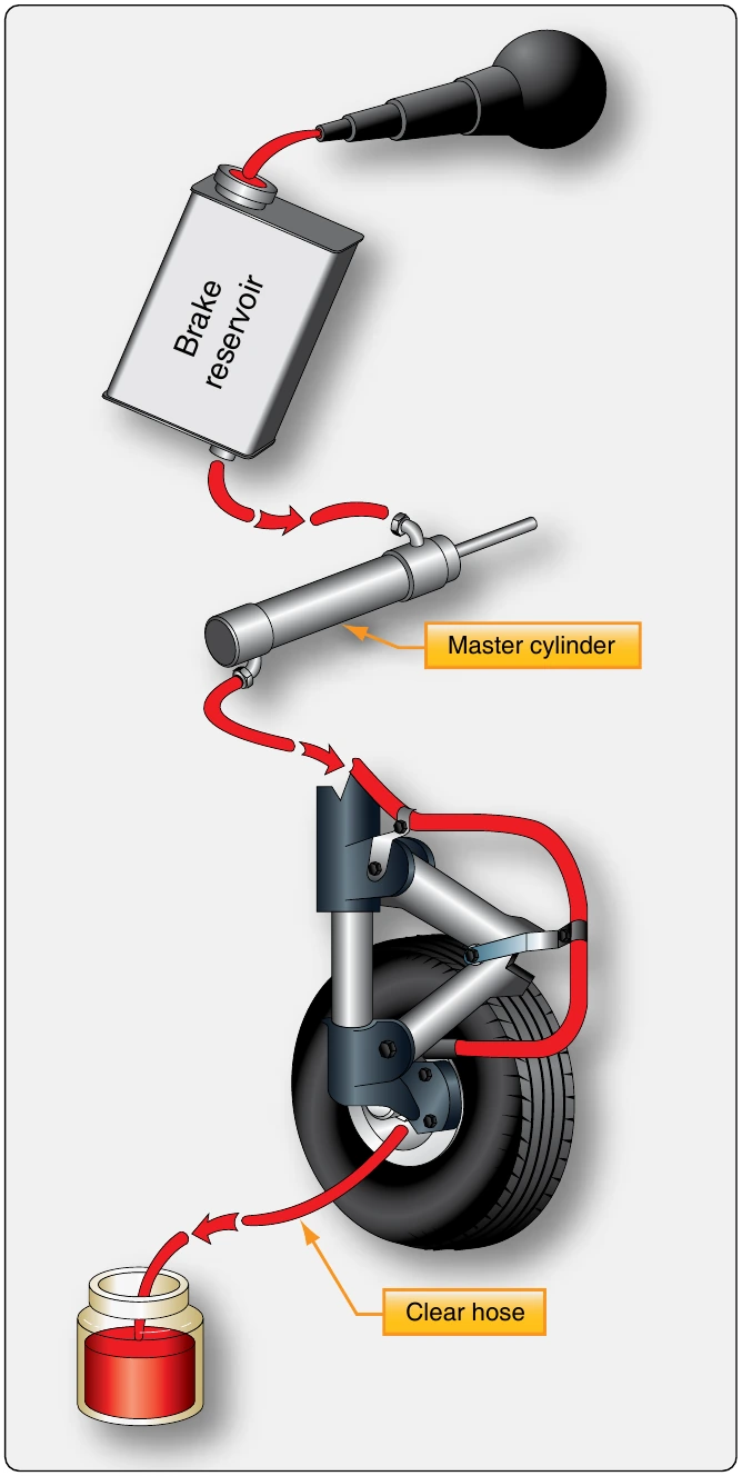
Whenever bleeding the brakes, ensure that reservoirs and bleed tanks remain full during the process. Use only clean, specified fluid.Always check the brakes for proper operation, any leaks when bleeding is complete, and assure that the fluid quantity level is correct.
Bleeding Power Brake Systems
Top down brake bleeding is used in power brake systems. Power brakes are supplied with fluid from the aircraft hydraulic system. The hydraulic system should operate without air in the fluid as should the brake system. Therefore, bottom up pressure bleeding is not an option for power brakes. The trapped air in the brake system would be forced into the main hydraulic system, which is not acceptable.
Many aircraft with power brake systems accept the connection of an auxiliary hydraulic mule that can be used to establish pressure in the system for bleeding. Regardless, the aircraft system must be pressurized to bleed power brake systems. Attach a clear hose to the brake bleed port fitting on the brake assembly and immerse the other end of the hose in a container of clean hydraulic fluid. With the bleeder valve open, carefully apply the brake to allow aircraft hydraulic fluid to enter the brake system. The fluid expels the fluid contaminated with air out of the bleed hose into the container. When air is no longer visible in the hose, close the bleed valve and restore the hydraulic system to normal operation configuration.
Power brake systems on different aircraft contain many variations and a wide array of components that may affect the proper bleeding technique to be followed. Consult the manufacturer’s maintenance information for the correct bleeding procedure for each aircraft. Be sure to bleed auxiliary and emergency brake systems when bleeding the normal brake system to ensure proper operation when needed.