
Chapter 13
Aircraft Landing Gear Systems
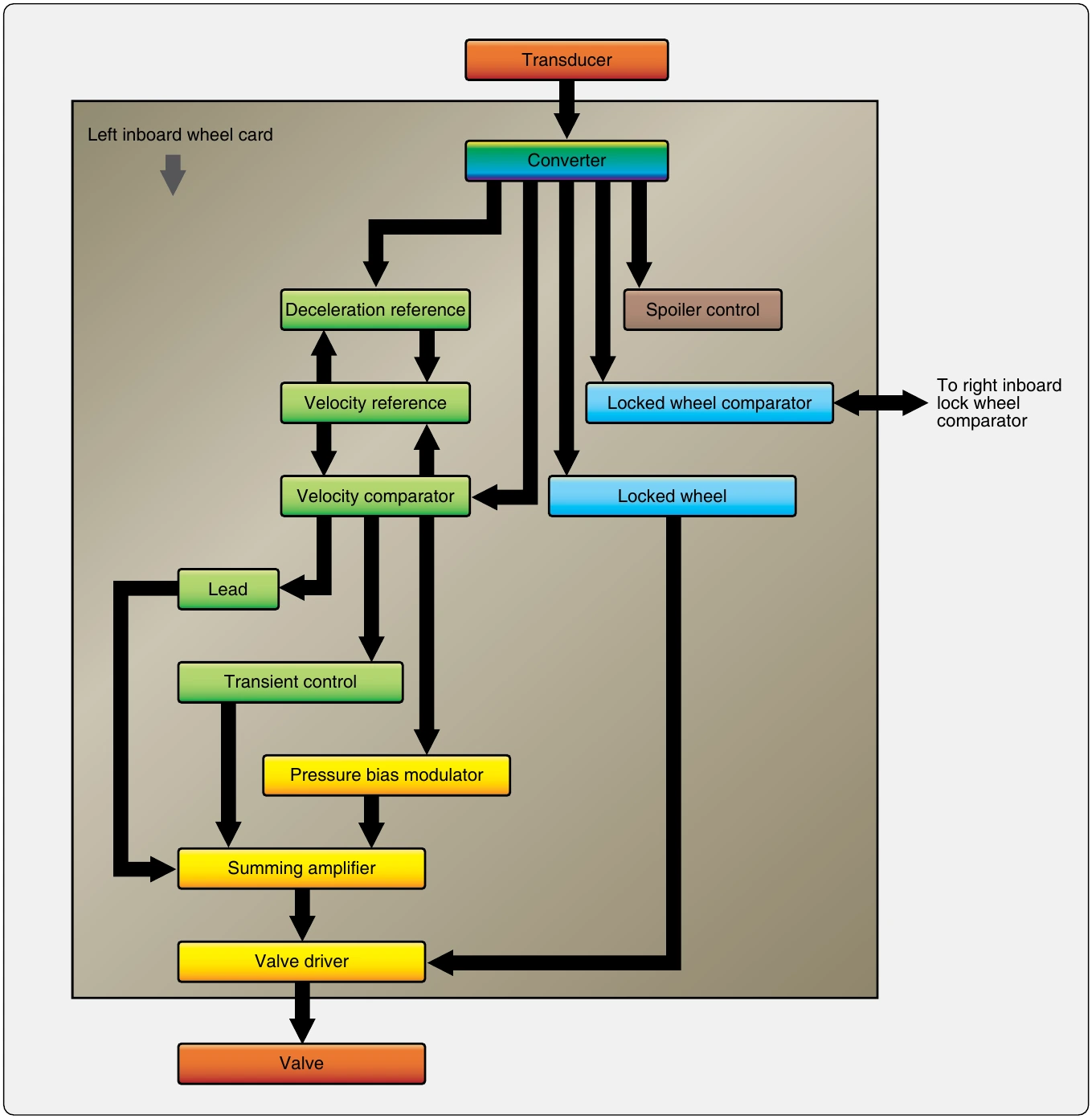
The converter shown changes the AC frequency received from the wheel sensor into DC voltage that is proportional to wheel speed. The output is used in a velocity reference loop that contains deceleration and velocity reference circuits. The converter also supplies input for the spoiler system and the locked wheel system, which is discussed at the end of this section. A velocity reference loop output voltage is produced, which represents the instantaneous velocity of the aircraft. This is compared to converter output in the velocity comparator. This comparison of voltages is essentially the comparison of the aircraft speed to wheel speed. The output from the velocity comparator is a positive or negative error voltage corresponding to whether the wheel speed is too fast or too slow for optimum braking efficiency for a given aircraft speed.
The error output voltage from the comparator feeds the pressure bias modulator circuit. This is a memory circuit that establishes a threshold where the pressure to the brakes provides optimum braking. The error voltage causes the modulator to either increase or decrease the pressure to the brakes in attempt to hold the modulator threshold. It produces a voltage output that is sent to the summing amplifier to do this. A lead output from the comparator anticipates when the tire is about to skid with a voltage that decreases the pressure to the brake. It sends this voltage to the summing amplifier as well. A transient control output from the comparator designed for rapid pressure dump when a sudden skid has occurred also sends voltage to the summing amp. As the name suggests, the input voltages to the amplifier are summed, and a composite voltage is sent to the valve driver. The driver prepares the current required to be sent to the control valve to adjust the position of the valve. Brake pressure increases, decreases, or holds steady depending on this value.
Anti-Skid Control Valves
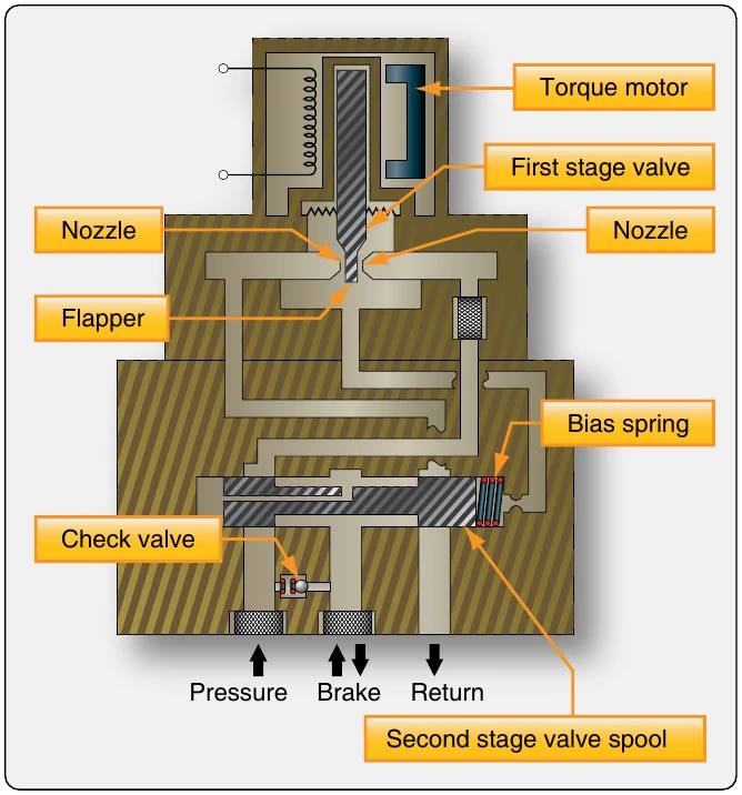
Anti-skid control valves are fast-acting, electrically controlled hydraulic valves that respond to the input from the anti-skid control unit. There is one control valve for each brake assembly. A torque motor uses the input from the valve driver to adjust the position of a flapper between two nozzles. By moving the flapper closer to one nozzle or the other, pressures are developed in the second stage of the valve. These pressures act on a spool that is positioned to build or reduce pressure to the brake by opening and blocking fluid ports. [Figure 13-111]
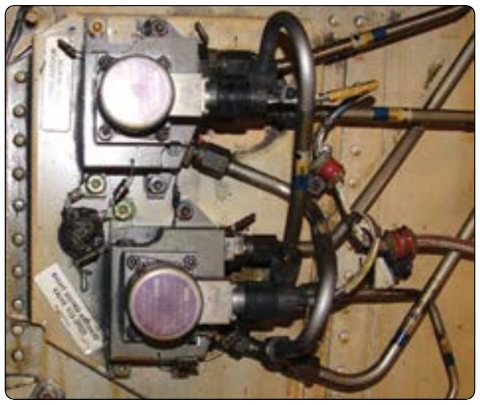
As pressure is adjusted to the brakes, deceleration slows to within the range that provides the most effective braking without skidding. The wheel sensor signal adjusts to the wheel speed, and the control unit processes the change. Output is altered to the control valve. The control valve flapper position is adjusted and steady braking resumes without correction until needed. Anti-skid control valves are typically located in the main wheel for close access to hydraulic pressure and return manifolds, as well as the brake assemblies. [Figure 13-112] Systematically, they are positioned downstream of the power brake control valves but upstream of debooster cylinders if the aircraft is so equipped as was shown in Figure 13-104.
Touchdown & Lock Wheel Protection
It is essential that the brakes are not applied when the aircraft contacts the runway upon landing. This could cause immediate tire blowout. A touchdown protection mode is built into most aircraft anti-skid systems to prevent this. It typically functions in conjunction with the wheel speed sensor and the air/ground safety switch on the landing gear strut (squat switch). Until the aircraft has weight on wheels, the detector circuitry signals the anti-skid control valve to open the passage between the brakes and the hydraulic system return, thus preventing pressure build-up and application of the brakes. Once the squat switch is open, the anti-skid control unit sends a signal to the control valve to close and permit brake pressure build-up. As a back-up and when the aircraft is on the ground with the strut not compressed enough to open the squat switch, a minimum wheel speed sensor signal can override and allow braking. Wheels are often grouped with one relying on the squat switch and the other on wheel speed sensor output to ensure braking when the aircraft is on the ground, but not before then.
Locked wheel protection recognizes if a wheel is not rotating. When this occurs, the anti-skid control valve is signaled to fully open. Some aircraft anti-skid control logic, such as the Boeing 737 shown in Figure 13-111, expands the locked wheel function. Comparator circuitry is used to relieve pressure when one wheel of a paired group of wheels rotates 25 percent slower than the other. Inboard and outboard pairs are used because if one of the pair is rotating at a certain speed, so should the other. If it is not, a skid is beginning or has occurred.
On takeoff, the anti-skid system receives input through a switch located on the gear selector that shuts off the anti-skid system. This allows the brakes to be applied as retraction occurs so that no wheel rotation exists while the gear is stowed.
Auto Brakes
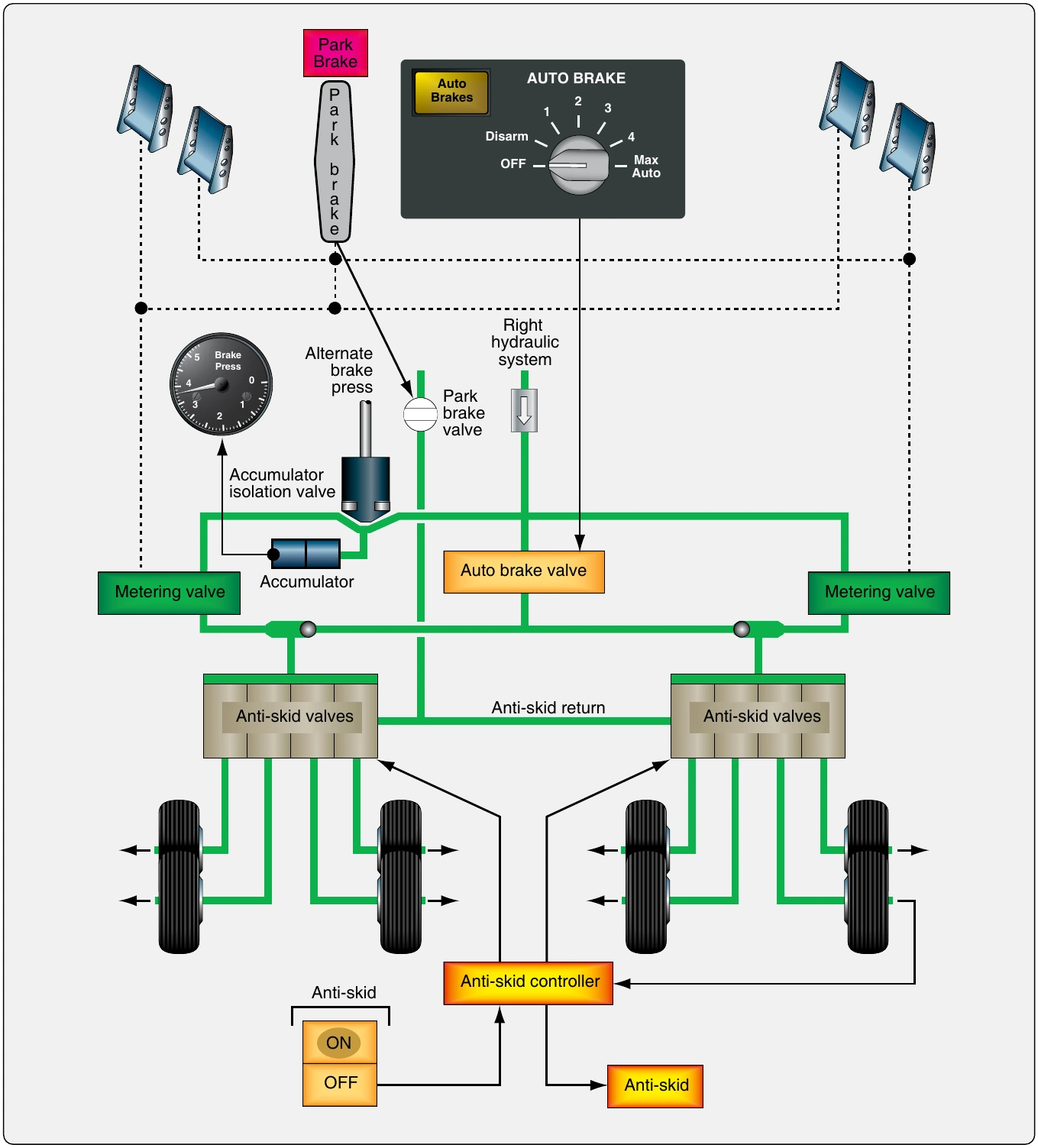
Aircraft equipped with auto brakes typically bypass the brake control valves or brake metering valves and use a separate auto brake control valve to provide this function. In addition to the redundancy provided, auto brakes rely on the anti-skid system to adjust pressure to the brakes if required due to an impending skid. Figure 13-113 shows a simplified diagram of the Boeing 757 brake system with the auto brake valve in relation to the main metering valve and anti-skid valves in this eight-main wheel system.
Anti-Skid System Tests
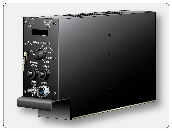
It is important to know the status of the anti-skid system prior to attempting to use it during a landing or aborted takeoff. Ground tests and in-flight tests are used. Built-in test circuits and control features allow testing of the system components and provide warnings should a particular component or part of the system become inoperative. An inoperative anti-skid system can be shut off without affecting normal brake operation.
Ground Test
Ground tests vary slightly from aircraft to aircraft. Consult the manufacturer’s maintenance manual for test procedures specific to the aircraft in question.