Chapter 13
Aircraft Landing Gear Systems
Much of the anti-skid system testing originates from testing circuits in the anti-skid control unit. Built-in test circuits continuously monitor the anti-skid system and provide warning if a failure occurs. An operational test can be performed before flight. The anti-skid control switch and/or test switch is used in conjunction with system indicator light(s) to determine system integrity. A test is first done with the aircraft at rest and then in an electrically simulated anti-skid braking condition. Some anti-skid control units contain system and component testing switches and lights for use by the technician. This accomplishes the same operational verification but allows an additional degree of troubleshooting. Test sets are available for anti-skid systems that produce electric signals that simulate speed outputs of the wheel transducer, deceleration rates, and flight/ground parameters.
In-Flight Test
In-flight testing of the anti-skid system is desirable and part of the pre-landing checklist so that the pilot is aware of system capability before landing. As with ground testing, a combination of switch positions and indicator lights are used according to information in the aircraft operations manual.
Anti-Skid System Maintenance
Anti-skid components require little maintenance. Troubleshooting anti-skid system faults is either performed via test circuitry or can be accomplished through isolation of the fault to one of the three main operating components of the system. Anti-skid components are normally not repaired in the field. They are sent to the manufacturer or a certified repair station when work is required. Reports of anti-skid system malfunction are sometimes malfunctions of the brake system or brake assemblies. Ensure brake assemblies are bled and functioning normally without leaks before attempting to isolate problems in the anti-skid system.
Wheel Speed Sensor
Wheel speed sensors must be securely and correctly mounted in the axle. The means of keeping contamination out of the sensor, such as sealant or a hub cap, should be in place and in good condition. The wiring to the sensor is subject to harsh conditions and should be inspected for integrity and security. It should be repaired or replaced if damaged in accordance with the manufacturer’s instructions. Accessing the wheel speed sensor and spinning it by hand or other recommended device to ensure brakes apply and release via the anti-skid system is common practice.
Control Valve
Anti-skid control valve and hydraulic system filters should be cleaned or replaced at the prescribed intervals. Follow all manufacturer’s instructions when performing this maintenance. Wiring to the valve must be secure, and there should be no fluid leaks.
Control Unit
Control units should be securely mounted. Test switches and indicators, if any, should be in place and functioning. It is essential that wiring to the control unit is secure. A wide variety of control units are in use. Follow the manufacturer’s instructions at all times when inspecting or attempting to perform maintenance on these units.
Brake Inspection & Service
Brake inspection and service is important to keep these critical aircraft components fully functional at all times. There are many different brake systems on aircraft. Brake system maintenance is performed both while the brakes are installed on the aircraft and when the brakes are removed. The manufacturer’s instructions must always be followed to ensure proper maintenance.
On Aircraft Servicing
Inspection and servicing of aircraft brakes while installed on the aircraft is required. The entire brake system must be inspected in accordance with manufacturer’s instructions. Some common inspection items include: brake lining wear, air in the brake system, fluid quantity level, leaks, and proper bolt torque.
Lining Wear
Brake lining material is made to wear as it causes friction during application of the brakes. This wear must be monitored to ensure it is not worn beyond limits and sufficient lining is available for effective braking. The aircraft manufacturer gives specifications for lining wear in its maintenance information. The amount of wear can be checked while the brakes are installed on the aircraft.
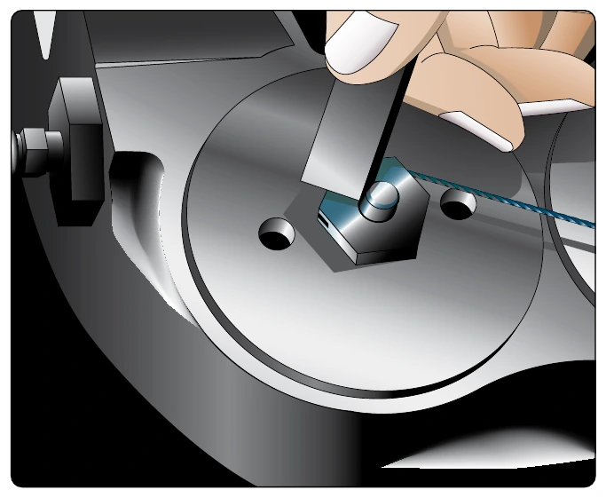
Many brake assemblies contain a built-in wear indicator pin. Typically, the exposed pin length decreases as the linings wear, and a minimum length is used to indicate the linings must be replaced. Caution must be used as different assemblies may vary in how the pin measured. On the Goodyear brake described above, the wear pin is measured where it protrudes through the nut of the automatic adjuster on the back side of the piston cylinder. [Figure 13-114] The Boeing brake illustrated in Figure 13-89 measures the length of the pin from the back of the pressure plate when the brakes are applied (dimension L). The manufacturer’s maintenance information must be consulted to ensure brake wear pin indicators on different aircraft are read correctly.
On many other brake assemblies, lining wear is not measured via a wear pin. The distance between the disc and a portion of the brake housing when the brakes are applied is sometimes used. As the linings wear, this distance increases. The manufacturer specified at what distance the linings should be changed. [Figure 13-115] On Cleveland brakes, lining wear can be measured directly, since part of the lining is usually exposed. The diameter of a number 40 twist drill is approximately equal to the minimum lining thickness allowed. [Figure 13-116]