Chapter 14
Aircraft Fuel Systems
Fuel System Indicators
Aircraft fuel systems utilize various indicators. All systems are required to have some sort of fuel quantity indicator. Fuel flow, pressure, and temperature are monitored on many aircraft. Valve position indicators and various warning lights and annunciations are also used.
Fuel Quantity Indicating Systems
All aircraft fuel systems must have some form of fuel quantity indicator. These devices vary widely depending on the complexity of the fuel system and the aircraft on which they are installed. Simple indicators requiring no electrical power were the earliest type of quantity indicators and are still in use today. The use of these direct reading indicators is possible only on light aircraft in which the fuel tanks are in close proximity to the flight deck. Other light aircraft and larger aircraft require electric indicators or electronic capacitance-type indicators.
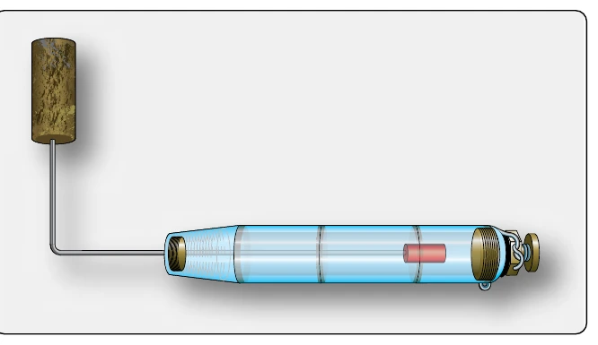
A sight glass is a clear glass or plastic tube open to the fuel tank that fills with fuel to the same level as the fuel in the tank. It can be calibrated in gallons or fractions of a full tank that can be read by the pilot. Another type of sight gauge makes use of a float with an indicating rod attached to it. As the float moves up and down with the fuel level in the tank, the portion of the rod that extends through the fuel cap indicates the quantity of fuel in the tank. [Figure 14-66] These two mechanisms are combined in yet another simple fuel quantity indicator in which the float is attached to a rod that moves up or down in a calibrated cylinder. [Figure 14-67]
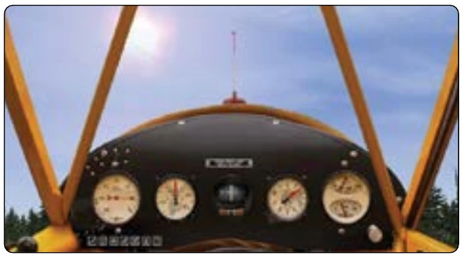
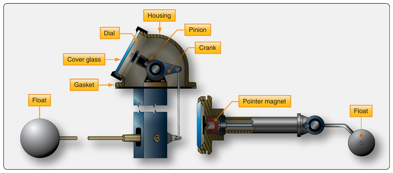
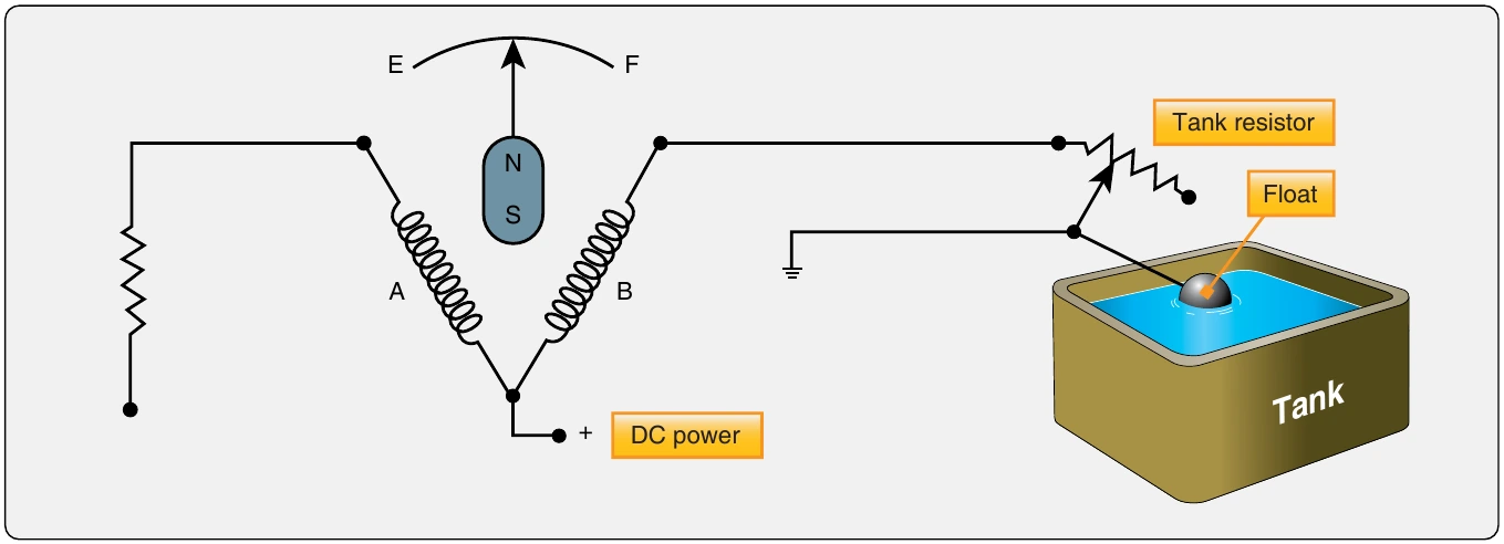
More sophisticated mechanical fuel quantity gauges are common. A float that follows the fuel level remains the primary sensing element, but a mechanical linkage is connected to move a pointer across the dial face of an instrument. This can be done with a crank and pinion arrangement that drives the pointer with gears, or with a magnetic coupling, to the pointer. [Figure 14-68] Electric fuel quantity indicators are more common than mechanical indicators in modern aircraft. Most of these units operate with direct current (DC) and use variable resistance in a circuit to drive a ratiometer-type indicator. The movement of a float in the tank moves a connecting arm to the wiper on a variable resistor in the tank unit. This resistor is wired in series with one of the coils of the ratiometer-type fuel gauge in the instrument panel. Changes to the current flowing through the tank unit resistor change the current flowing through one of the coils in the indicator. This alters the magnetic field in which the indicating pointer pivots. The calibrated dial indicates the corresponding fuel quantity. [Figure 14-69]
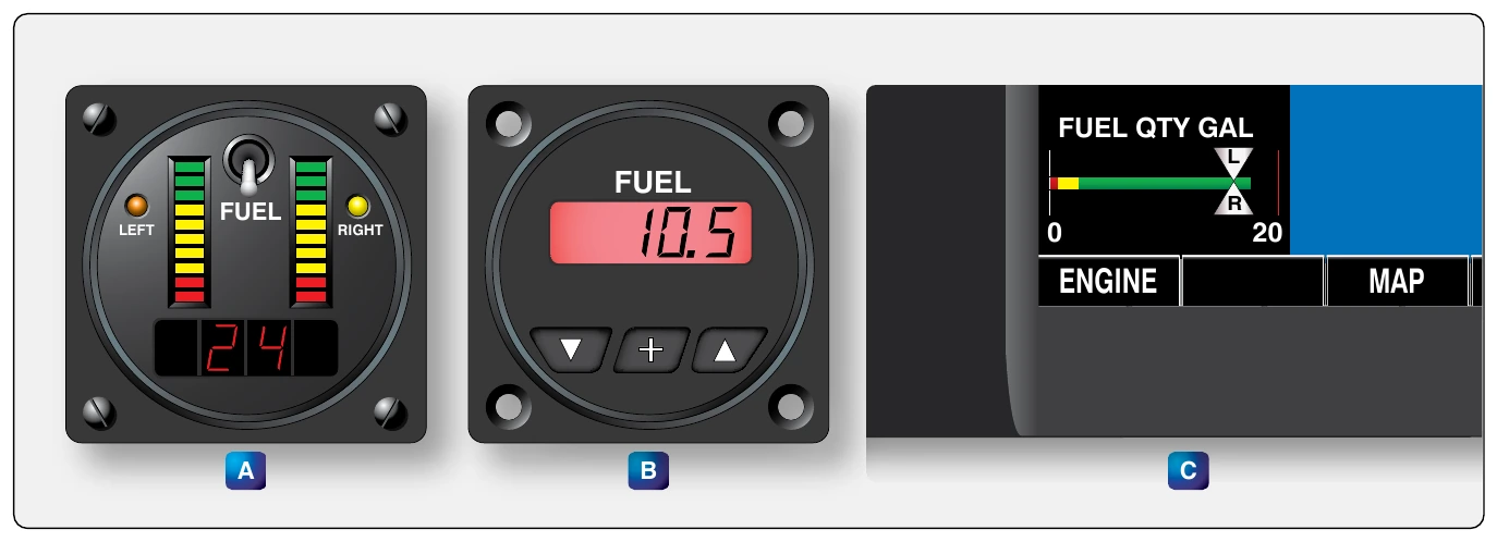
Digital indicators are available that work with the same variable resistance signal from the tank unit. They convert the variable resistance into a digital display in the flight deck instrument head. [Figure 14-70] Fully digital instrumentation systems, such as those found in a glass flight deck aircraft, convert the variable resistance into a digital signal to be processed in a computer and displayed on a flat screen panel.
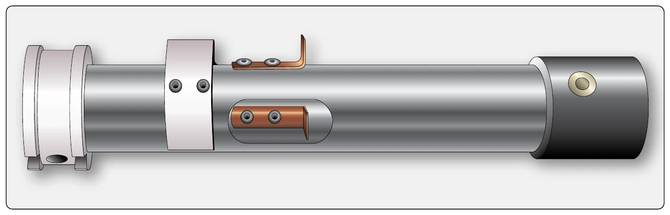
Large and high-performance aircraft typically utilize electronic fuel quantity systems. This is also known as a capacitance-type fuel quantity indicating system. These more costly systems have the advantage of having no moving parts in the tank sending units. Variable capacitance transmitters are installed in the fuel tanks extending from the top to the bottom of each tank in the usable fuel. Several of these tank units, or fuel probes as they are sometimes called, may be installed in a large tank. [Figure 14-71] They are wired in parallel. As the level of the fuel changes, the capacitance of each unit changes. The capacitance transmitted by all of the probes in a tank is totaled and compared in a bridge circuit by a microchip computer in the tank’s digital fuel quantity indicator in the flight deck. As the aircraft maneuvers, some probes are in more fuel than others due to the attitude of the aircraft. The indication remains steady, because the total capacitance transmitted by all of the probes remains the same. A trimmer is used to match the capacitance output with the precalibrated quantity indicator.
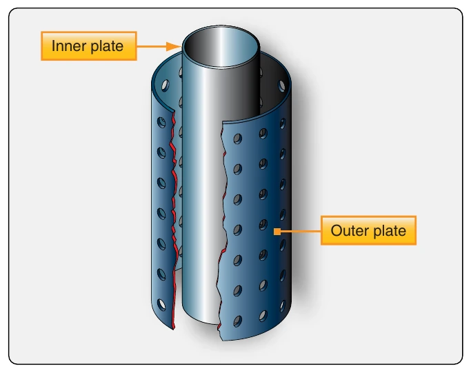
A capacitor is a device that stores electricity. The amount it can store depends on three factors: the area of its plates, the distance between the plates, and the dielectric constant of the material separating the plates. A fuel tank unit contains two concentric plates that are a fixed distance apart. Therefore, the capacitance of a unit can change if the dielectric constant of the material separating the plates varies. The units are open at the top and bottom, so they can assume the same level of fuel as is in the tanks. Therefore, the material between the plates is either fuel (if the tank is full), air (if the tank is empty), or some ratio of fuel and air depending on how much fuel remains in the tank. Figure 14-72 shows a simplified illustration of this construction.
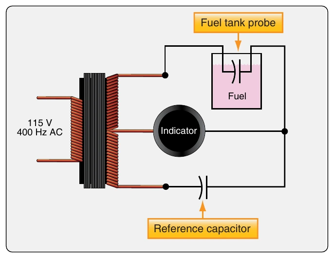
The bridge circuit that measures the capacitance of the tank units uses a reference capacitor for comparison. When voltage is induced into the bridge, the capacitive reactance of the tank probes and the reference capacitor can be equal or different. The magnitude of the difference is translated into an indication of the fuel quantity in the tank calibrated in pounds. Some European aircraft display this in kilograms (kg). Figure 14-73 represents the nature of this comparison bridge circuit.
The use of tank unit capacitors, a reference capacitor, and a microchip bridge circuit in the fuel quantity indicators is complicated by the fact that temperature affects the dielectric constant of the fuel. A compensator unit (mounted low in the tank so it is always covered with fuel) is wired into the bridge circuit. It modifies current flow to reflect temperature variations of the fuel, which affect fuel density and thus capacitance of the tank units. [Figure 14-74] An amplifier is also needed in older systems. The amplitude of the electric signals must be increased to move the servo motor in the analog indicator. Additionally, the dielectric constant of different turbine-engine fuels approved for a particular aircraft may also vary. Calibration is required to overcome this.