
Chapter 14
Aircraft Fuel Systems
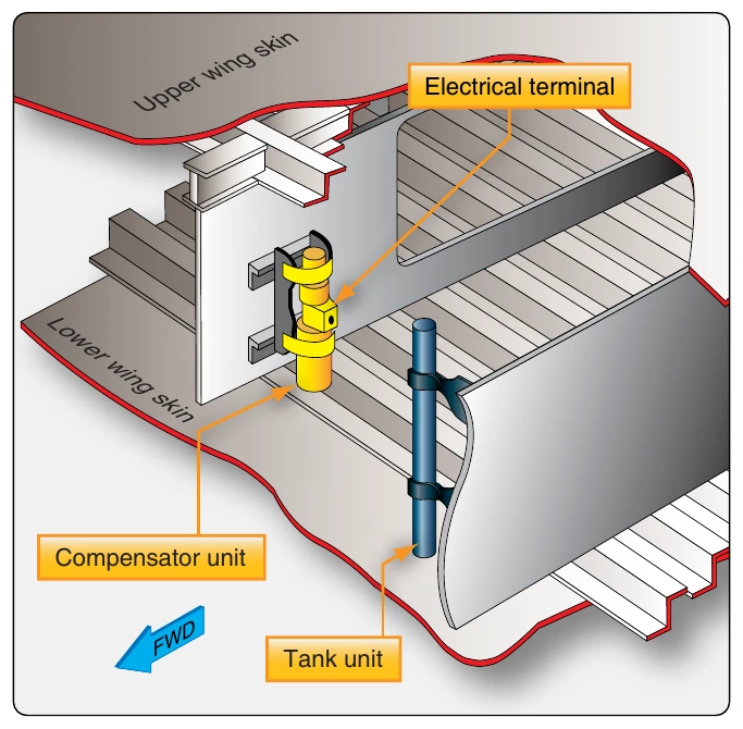
A fuel totalizer is part of the capacitance-type fuel quantity indication system. It is used to add the tank quantities from all indicators. This total aircraft fuel quantity can be used by the crew and by flight management computers for calculating optimum airspeed and engine performance limits for climb, cruise, descent, etc. Capacitance-type fuel quantity system test units are available for troubleshooting and ensuring proper functioning and calibration of the indicating system components.
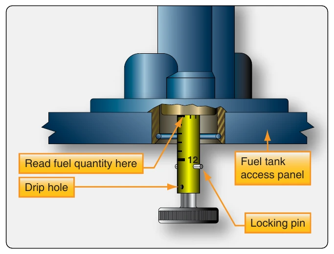
Many aircraft with capacitance-type fuel indicating systems also use a mechanical indication system to cross-check fuel quantity indications and to ascertain the amount of fuel onboard the aircraft when electrical power is not available. A handful of fuel measuring sticks, or drip sticks, are mounted throughout each tank. When pushed and rotated, the drip stick can be lowered until fuel begins to exit the hole on the bottom of each stick. This is the point at which the top of the stick is equal to the height of the fuel. The sticks have a calibrated scale on them. By adding the indications of all of the drip sticks and converting to pounds or gallons via a chart supplied by the manufacturer, the quantity of the fuel in the tank can be ascertained. [Figure 14-75]
Fuel Flow Meters
A fuel flow meter indicates an engine’s fuel use in real time. This can be useful to the pilot for ascertaining engine performance and for flight planning calculations. The types of fuel flow meter used on an aircraft depends primarily on the powerplant being used and the associated fuel system.
Measuring fuel flow accurately is complicated by the fact that the fuel mass changes with temperature or with the type of fuel used in turbine engines. In light aircraft with reciprocating engines, systems have been devised to measure fuel volume. The actual mass of fuel flowing to the engine is based on an assumption of the average weight of the fuel per unit volume.
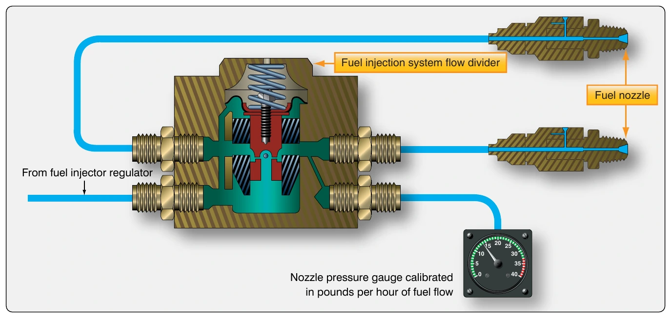
The simplest fuel flow sensing device is used in conjunction with fuel injection systems installed on horizontally opposed reciprocating engines. A pressure gauge is used but it is calibrated in gallons per hour or pounds per hour. The amount of fuel that is flowing through the fuel injectors has a direct relationship to the pressure drop across the fuel injector orifices. Therefore, monitoring fuel pressure at the injector(s) closely approximates fuel flow and provides useful flow information for mixture control and flight planning.
There is a major limitation to the use of fuel pressure as a flow indicator. Should an injector become clogged, fuel flow is reduced. However, the pressure gauge indicates a higher fuel pressure (and greater fuel flow) due to the restriction. Operators must be aware of this potential condition and check the flow meter against EGT to determine the nature of the elevated indication. [Figure 14-76]
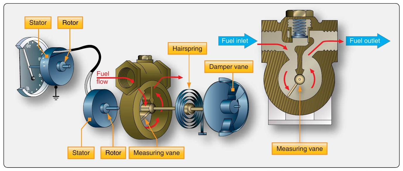
Large reciprocating engine fuel systems may use a vane-type fuel flow meter that measures the volume of the fuel consumed by the engine. The fuel flow unit is typically located between the engine-driven fuel pump and the carburetor. The entire volume of fuel delivered to the engine is made to pass through the flow meter. Inside, the fuel pushes against the vane, which counters the force of the fuel flow with a calibrated spring. The vane shaft rotates varying degrees matching the fuel flow rate through the unit. An autosyn transmitter deflects the pointer on the flight deck fuel flow gauge the same amount as the vane deflects. The dial face of the indicator is calibrated in gallons per hour or pounds per hour based on an average weight of fuel.
Since fuel fed to the engine must pass through the flow meter unit, a relief valve is incorporated to bypass the fuel around the vane should it malfunction and restrict normal fuel flow. The vane chamber is eccentric. As more fuel pushes against the vane, it rotates further around in the chamber. The volume of the chamber gradually increases to permit the greater flow of fuel without restriction or pressure buildup. [Figure 14-77]
Turbine-engine aircraft experience the greatest range of fuel density from temperature variation and fuel composition. An elaborate fuel flow device is used on these aircraft. It measures fuel mass for accurate fuel flow indication in the flight deck. The mass flow indicator takes advantage of the direct relationship between fuel mass and viscosity. Fuel is swirled by a cylindrical impeller that rotates at a fixed speed. The outflow deflects a turbine just downstream of the impeller. The turbine is held with calibrated springs. Since the impeller motor swirls, the fuel at a fixed rate, any variation of the turbine deflection is caused by the volume and viscosity of the fuel. The viscosity component represents the mass of the fuel. [Figure 14-78]
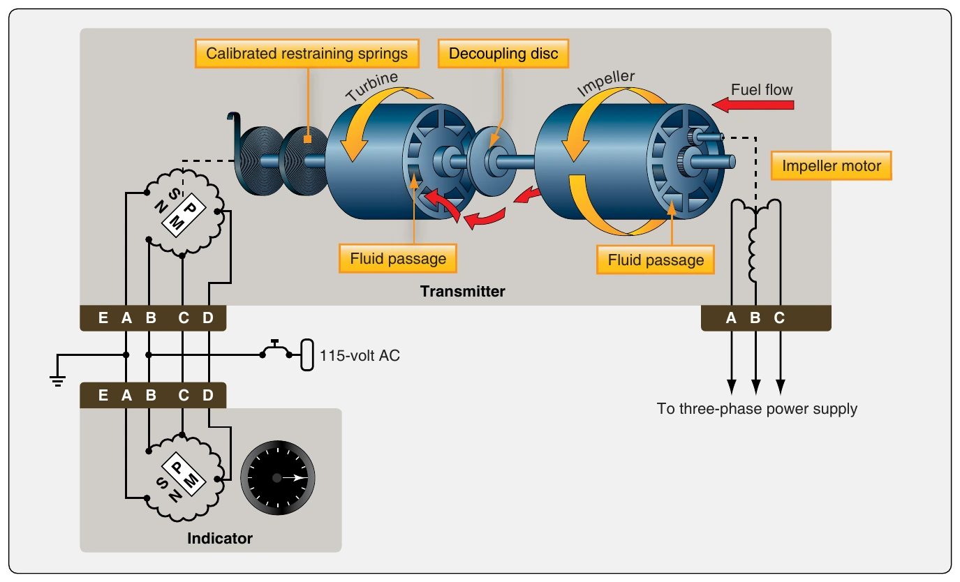
An alternating current (AC) synchro system is part of the mass fuel flow meter. It is used to position a pointer against the flight deck indicator scale calibrated in pounds per hour.
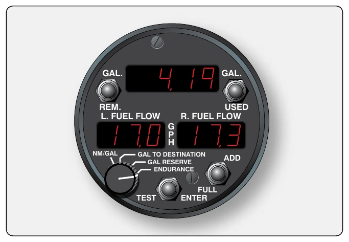
With accurate fuel flow knowledge, numerous calculations can be performed to aid the pilot’s situational awareness and flight planning. Most high-performance aircraft have a fuel totalizer that electronically calculates and displays information, such as total fuel used, total fuel remaining onboard the aircraft, total range and flight time remaining at the present airspeed, rate of fuel consumption, etc. On light aircraft, it is common to replace the original analog fuel indicators with electronic gauges containing similar capabilities and built-in logic. Some of these fuel computers, as they are called, integrate global positioning satellite (GPS) location information. [Figure 14-79] Aircraft with fully digital flight decks process fuel flow data in computers and display a wide array of fuel flow related information on demand.
Relatively new types of fuel flow sensors/transmitters are available in new aircraft and for retrofit to older aircraft. One type of device found in home-built and experimental aircraft uses a turbine that rotates in the fuel flow. The higher the flow rate is, the faster the turbine rotates. A Hall effect transducer is used to convert the speed of the turbine to an electrical signal to be used by an advanced fuel gauge similar to a fuel computer to produce a variety of calculated readouts and warnings. The turbine in this unit is in line with the fuel flow but is fail-safe to allow adequate fuel flow without interruption should the unit malfunction. [Figure 14-80]
Another fuel flow sensor used primarily on light aircraft also detects the spinning velocity of a turbine in the fuel path. It too has a fail-safe design should the turbine malfunction. In this unit, notches in the rotor interrupt an infrared light beam between an LED and phototransistor that creates a signal proportional to the amount fuel flow. [Figure 14-81] This type of sensor may be coupled with an electronic indicator.