
Chapter 14
Aircraft Fuel Systems
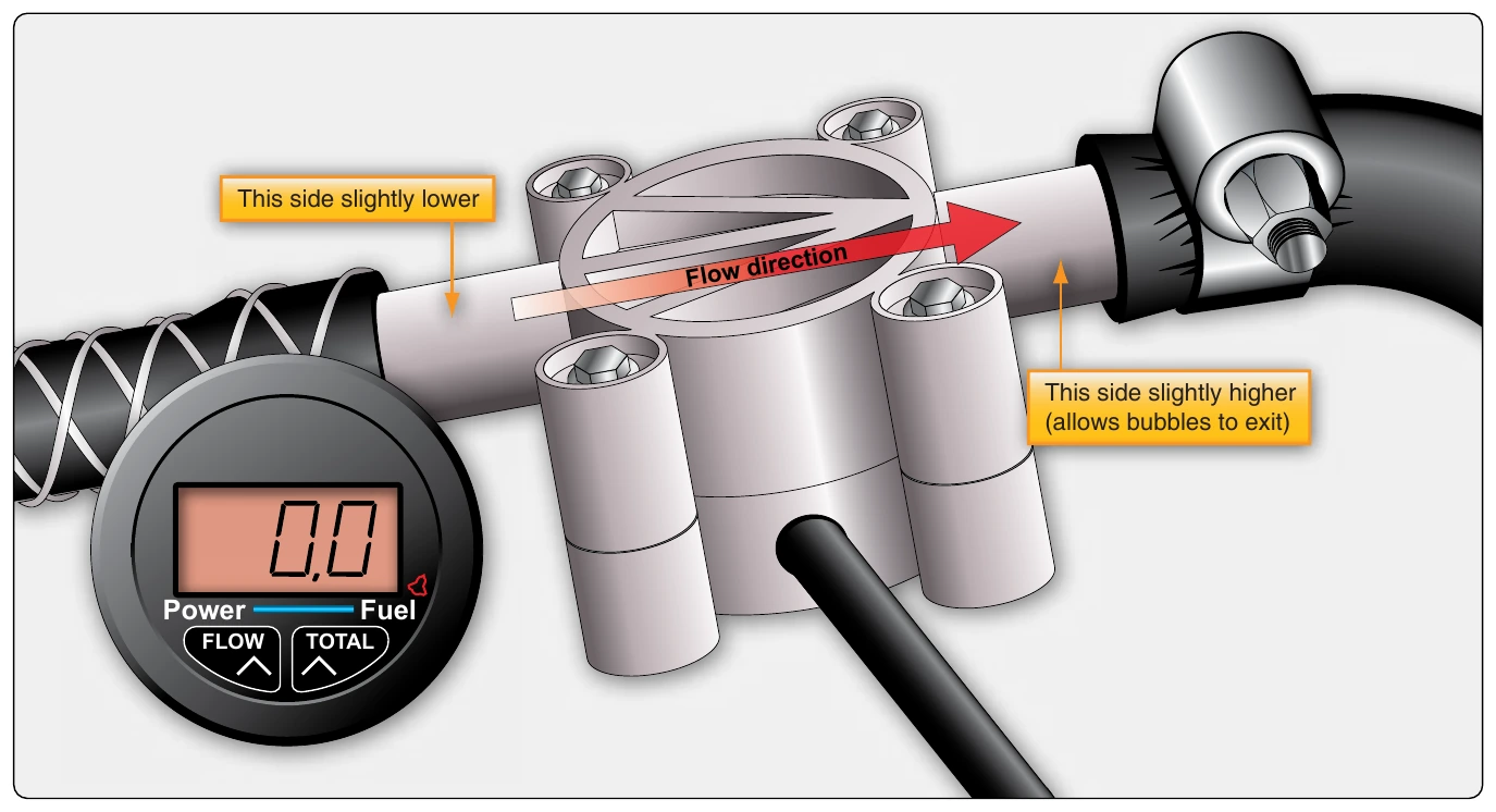
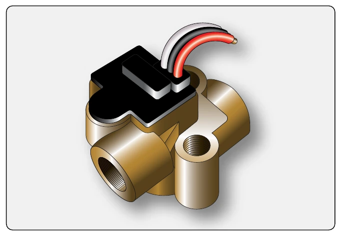
Increasing use of microprocessors and computers on aircraft enable the integration of fuel temperature and other compensating factors to produce highly accurate fuel flow information. Fuel flow sensing with digital output facilitates this with a high degree of reliability. Thermal dispersion technology provides flow sensing with no moving parts and digital output signals. The sensor consists of two resistance temperature detectors (RTDs). One is a reference RTD that measures the temperature of the fuel. The other is the active RTD. It is heated by an adjacent element to a temperature higher than the fuel. As the fuel flows, the active element cools proportionally to the fuel flow. The temperature difference between the two RTDs is highest at no flow.
The RTDs are connected to an electronic assembly that supplies power to the heater and uses sensing circuitry and a microprocessor to control a constant temperature difference between the heated and unheated RTDs. The electrical current to the heater is proportional to the mass flow of the fuel. As mentioned, the reference RTD is used as a temperature sensor to provide a temperature output and allow for temperature compensation of the flow measurement. [Figure 14-82]
Fuel Temperature Gauges
As previously mentioned, monitoring fuel temperature can inform the pilot when fuel temperature approaches that which could cause ice to form in the fuel system, especially at the fuel filter. Many large and high-performance turbine aircraft use a resistance type electric fuel temperature sender in a main fuel tank for this purpose. It can display on a traditional ratiometer gauge [Figure 14-65] or can be input into a computer for processing and digital display. A low fuel temperature can be corrected with the use of a fuel heater if the aircraft is so equipped. Also as mentioned, fuel temperature can be integrated into fuel flow processing calculations. Viscosity differences at varying fuel temperatures that affect fuel flow sensing accuracy can be corrected via microprocessors and computers.
Fuel Pressure Gauges
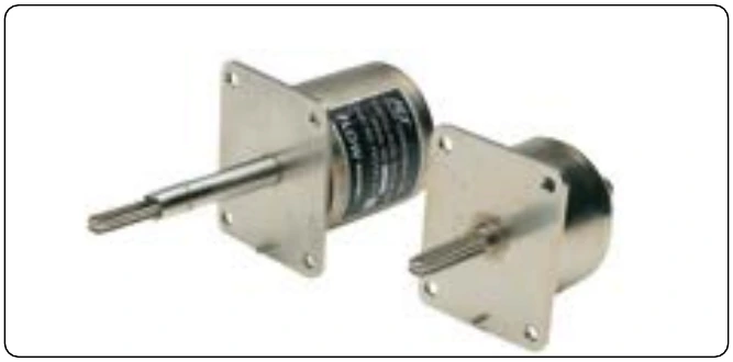
Monitoring fuel pressure can give the pilot early warning of a fuel system related malfunction. Verification that the fuel system is delivering fuel to the fuel metering device can be critical. Simple light reciprocating-engine aircraft typically utilize a direct reading Bourdon tube pressure gauge. It is connected into the fuel inlet of the fuel metering device with a line extending to the back of the gauge in the flight deck instrument panel. A more complex aircraft may have a sensor with a transducer located at the fuel inlet to the metering device that sends electrical signals to a flight deck gauge. [Figure 14-83] In aircraft equipped with an auxiliary pump for starting and to back up the engine-driven pump, the fuel pressure gauge indicates the auxiliary pump pressure until the engine is started. When the auxiliary pump is switched off, the gauge indicates the pressure developed by the engine-driven pump.
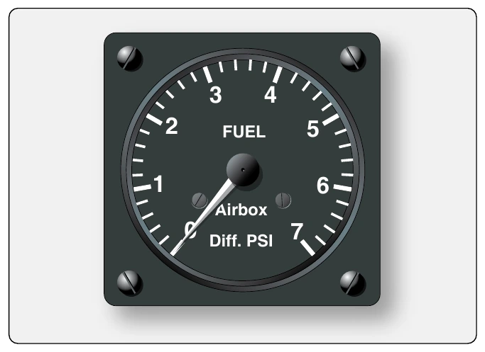
More complex and larger reciprocating engine aircraft may use a differential fuel pressure gauge. It compares fuel inlet pressure to the air inlet pressure at the fuel metering device. A bellows type pressure gauge is normally used. [Figure 14- 84]
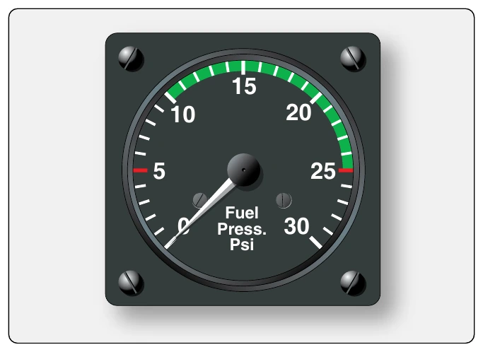
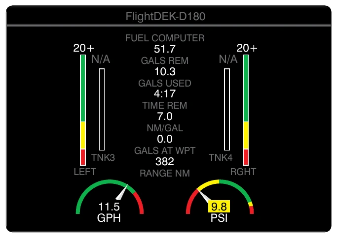
Modern aircraft may use a variety of sensors including solid state types and those with digital output signals or signals that are converted to digital output. These can be processed in the instrument gauge microprocessor, if so equipped, or in a computer and sent to the display unit. [Figure 14-85]
Pressure Warning Signal
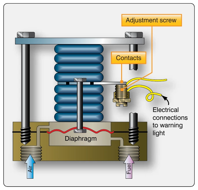
On aircraft of any size, visual and audible warning devices are used in conjunction with gauge indications to draw the pilot’s attention to certain conditions. Fuel pressure is an important parameter that merits the use of a warning signal when it falls outside of the normal operating range. Low fuel pressure warning lights can be illuminated through the use of simple pressure sensing switches. [Figure 14-86] The contacts of the switch will close when fuel pressure against the diaphragm is insufficient to hold them open. This allows current to flow to the annunciator or warning light in the flight deck.
Most turbine-powered aircraft utilize a low-pressure warning switch at the outlet of each fuel boost pump. The annunciator for each is typically positioned adjacent to the boost pump ON/OFF switch on the fuel panel in the flight deck. [Figure 14-87]
Valve-In-Transit Indicator Lights
Aircraft with multiple fuel tanks use valves and pumps to move fuel and to have it flow to desired locations, such as the engines, a certain tank, or overboard during fuel jettison. The functioning of the valves in the fuel system is critical.