
Chapter 15
Ice & Rain Protection
Ice can be detected visually, but most modern aircraft have one or more ice detector sensors that warn the flight crew of icing conditions. An annunciator light comes on to alert the flight crew. In some aircraft models, multiple ice detectors are used, and the ice detection system automatically turns on the WAI systems when icing is detected. [Figure 15-4]
Ice Prevention
Several means to prevent or control ice formation are used in aircraft today:
- Heating surfaces with hot air.
- Heating by electrical elements.
- Breaking up ice formations, usually by inflatable boots.
- Chemical application.
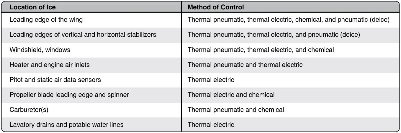
Equipment is designed for anti-icing or for deicing. Anti-icing equipment is turned on before entering icing conditions and is designed to prevent ice from forming. A surface may be anti-iced by keeping it dry, by heating to a temperature that evaporates water upon impingement, or by heating the surface just enough to prevent freezing, maintaining it running wet. Deicing equipment is designed to remove ice after it begins to accumulate typically on the wings and stabilizer leading edges. Ice may be controlled on aircraft structure by the methods described in Figure 15-5.
Wing & Stabilizer Anti-Icing Systems
The wing leading edges, or leading-edge slats, and horizontal and vertical stabilizer leading edges of many aircraft make and models have anti-icing systems installed to prevent the formation of ice on these components. The most common anti-icing systems used are thermal pneumatic, thermal electric, and chemical. Most general aviation (GA) aircraft equipped to fly in icing conditions use pneumatic deicing boots or a chemical anti-ice system. High-performance aircraft may have “weeping wings.” Large transport-category aircraft are equipped with advanced thermal pneumatic or thermal electric anti-icing systems that are controlled automatically to prevent the formation of ice.
Thermal Pneumatic Anti-icing
Thermal systems used for the purpose of preventing the formation of ice or for deicing airfoil leading edges usually use heated air ducted spanwise along the inside of the leading edge of the airfoil and distributed around its inner surface. These thermal pneumatic anti-icing systems are used for wings, leading edge slats, horizontal and vertical stabilizers, engine inlets, and more. There are several sources of heated air, including hot bleed air from the turbine compressor, engine exhaust heat exchangers, and ram air heated by a combustion heater.
Wing Anti-Ice (WAI) System
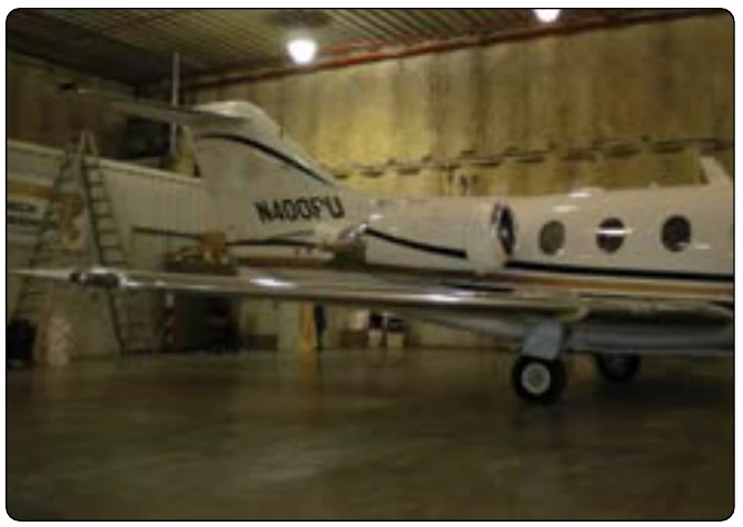
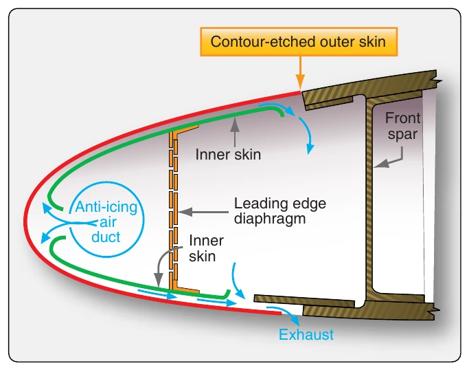
Thermal wing anti-ice (WAI or TAI) systems for business jet and large-transport category aircraft typically use hot air bled from the engine compressor. [Figure 15-6] Relatively large amounts of very hot air can be bled off the compressor, providing a satisfactory source of anti-icing heat. The hot air is routed through ducting, manifolds, and valves to components that need to be anti-iced. Figure 15-7 shows a typical WAI system schematic for a business jet. The bleed air is routed to each wing leading edge by an ejector in each wing inboard area. The ejector discharges the bleed air into piccolo tubes for distribution along the leading edge. Fresh ambient air is introduced into the wing leading edge by two flush-mounted ram air scoops in each wing leading edge, one at the wing root and one near the wingtip. The ejectors entrain ambient air, reduce the temperature of the bleed air, and increase the mass airflow in the piccolo tubes. The wing leading edge is constructed of two skin layers separated by a narrow passageway. [Figure 15-8] The air directed against the leading edge can only escape through the passageway, after which it is vented overboard through a vent in the bottom of the wingtip.
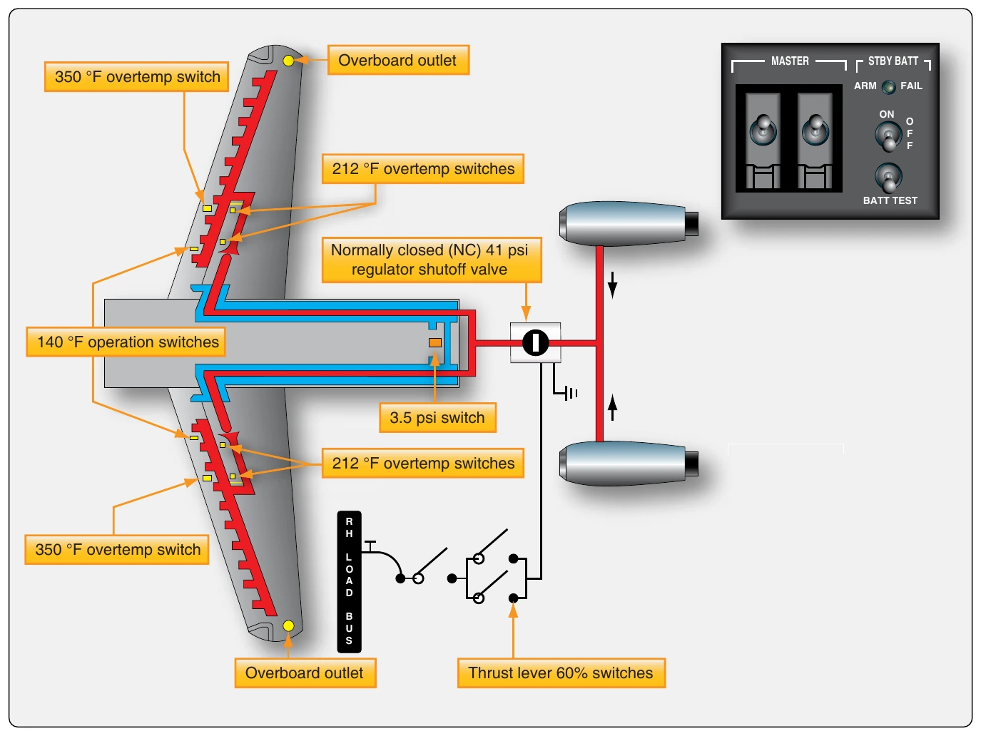
When the WAI switch is turned on, the pressure regulator is energized, and the shutoff valve opens. When the wing leading edge temperature reaches approximately +140 °F, temperature switches turn on the operation light above the switch. If the temperature in the wing leading edge exceeds approximately +212 °F (outboard) or +350 °F (inboard), the red WING OV HT warning light on the annunciator panel illuminates.
The ducting of WAI systems usually consists of aluminum alloy, titanium, stainless steel, or molded fiberglass tubes. The tube, or duct, sections are attached to each other by bolted end flanges or by band-type V-clamps. The ducting is lagged with a fire-resistant, heat-insulating material, such as fiberglass. In some installations, thin stainless-steel expansion bellows are used. Bellows are located at strategic positions to absorb any distortion or expansion of the ducting that may occur due to temperature variations. The joined sections of ducting are hermetically sealed by sealing rings. These seals are fitted into annular recesses in the duct joint faces.
When installing a section of duct, make certain that the seal bears evenly against and is compressed by the adjacent joint’s flange. When specified, the ducts should be pressure tested at the pressure recommended by the manufacturer of the aircraft concerned. Leak checks are made to detect defects in the duct that would permit the escape of heated air. The rate of leakage at a given pressure should not exceed that recommended in the aircraft maintenance manual.
Air leaks can often be detected audibly and are sometimes revealed by holes in the lagging or thermal insulation material. However, if difficulty arises in locating leaks, a soap-and-water solution may be used. All ducting should be inspected for security, general condition, or distortion. Lagging or insulating blankets must be checked for security and must be free of flammable fluids, such as oil or hydraulic fluid.