Chapter 16
Cabin Environmental Control Systems
While pressurization systems on different aircraft operate similarly with similar components, it cannot be assumed that they are the same. Even those systems constructed by a single manufacturer likely have differences when installed on different aircraft. It is important to check the aircraft manufacture’s service information when troubleshooting the pressurization system. A fault, such as failure to pressurize or failure to maintain pressurization, can have many different causes. Adherence to the steps in a manufacturer’s troubleshooting procedures is highly recommended to sequentially evaluate possible causes. Pressurization system test kits are available, or the aircraft can be pressurized by its normal sources during troubleshooting. A test flight may be required after maintenance.
Air Conditioning Systems
There are two types of air conditioning systems commonly used on aircraft. Air cycle air conditioning is used on most turbine-powered aircraft. It makes use of engine bleed air or APU pneumatic air during the conditioning process. Vapor cycle air conditioning systems are often used on reciprocating aircraft. This type system is similar to that found in homes and automobiles. Note that some turbine-powered aircraft also use vapor cycle air conditioning.
Air Cycle Air Conditioning
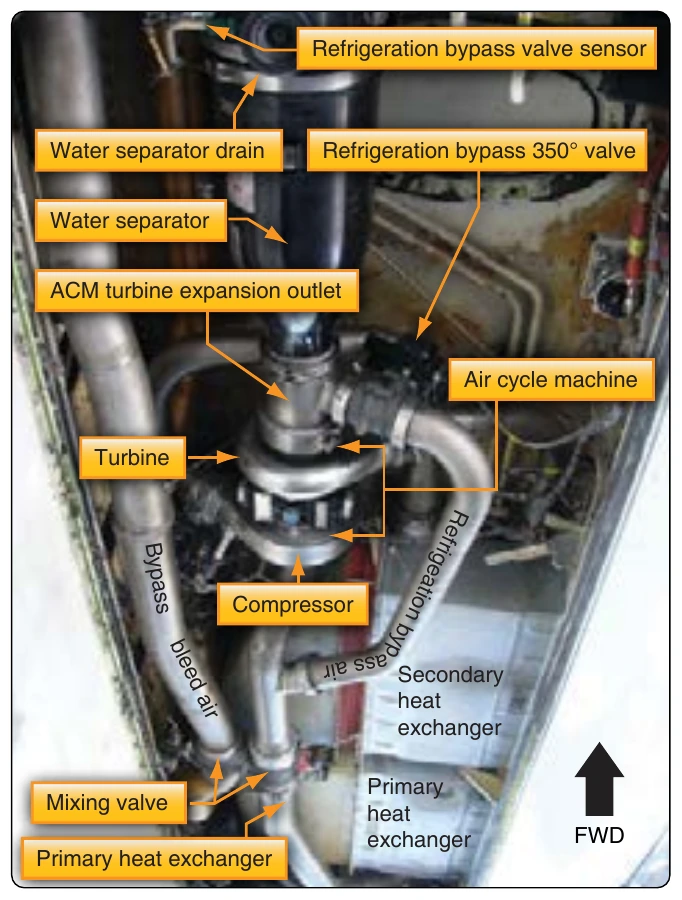
Air cycle air conditioning prepares engine bleed air to pressurize the aircraft cabin. The temperature and quantity of the air must be controlled to maintain a comfortable cabin environment at all altitudes and on the ground. The air cycle system is often called the air conditioning package or pack. It is usually located in the lower half of the fuselage or in the tail section of turbine-powered aircraft. [Figure 16-62]
System Operation
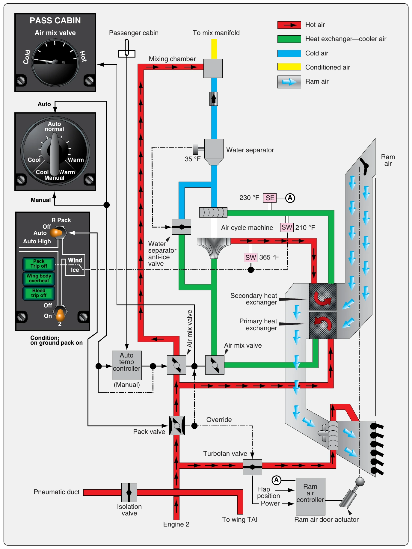
Even with the frigid temperatures experienced at high altitudes, bleed air is too hot to be used in the cabin without being cooled. It is let into the air cycle system and routed through a heat exchanger where ram air cools the bleed air. This cooled bleed air is directed into an air cycle machine. There, it is compressed before flowing through a secondary heat exchange that cools the air again with ram air. The bleed air then flows back into the air cycle machine where it drives an expansion turbine and cools even further. Water is then removed, and the air is mixed with bypassed bleed air for final temperature adjustment. It is sent to the cabin through the air distribution system. By examining the operation of each component in the air cycle process, a better understanding can be developed of how bleed air is conditioned for cabin use. Refer to Figure 16-63, which diagrams the air cycle air conditioning system of the Boeing 737.
Pneumatic System Supply
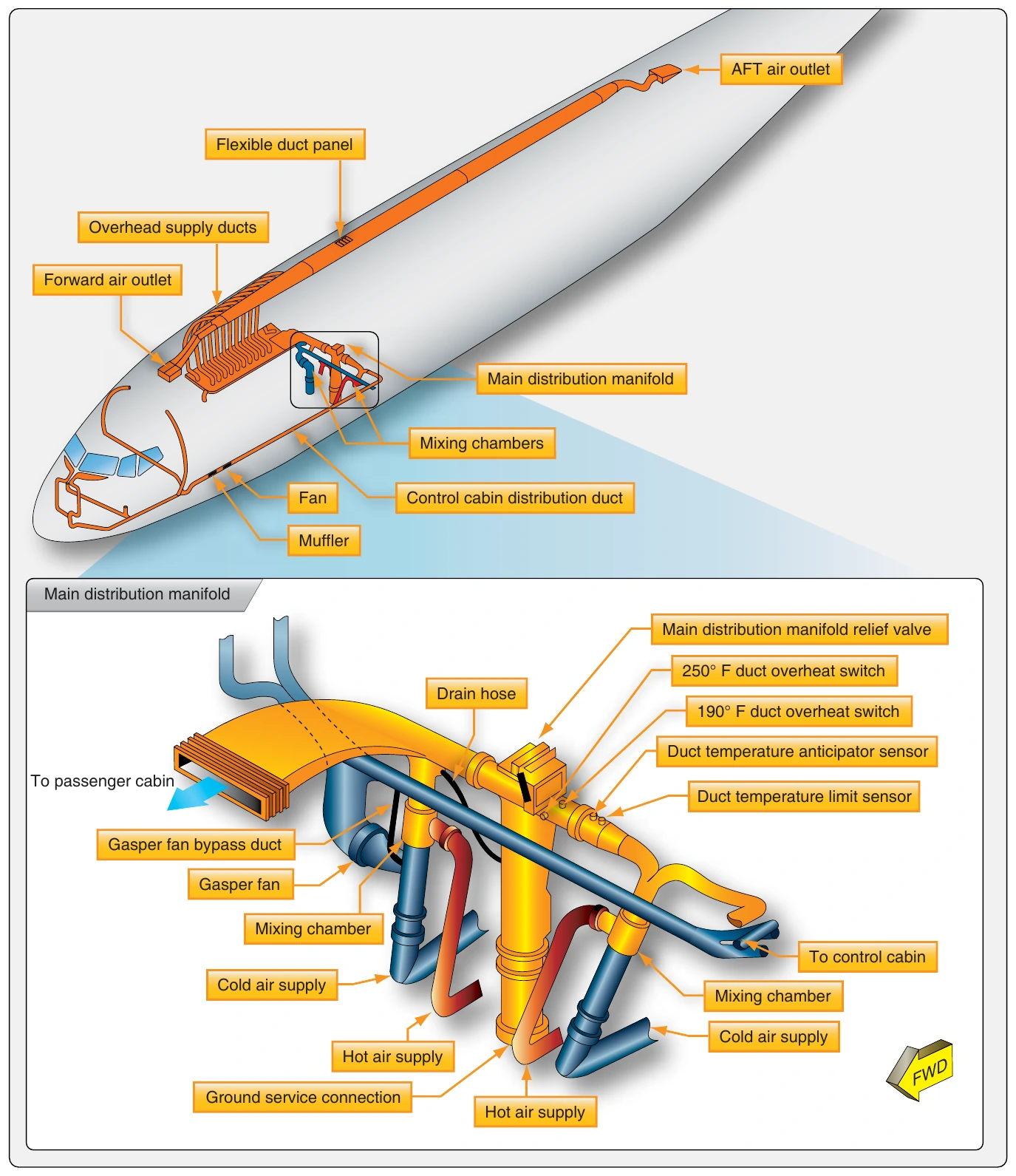
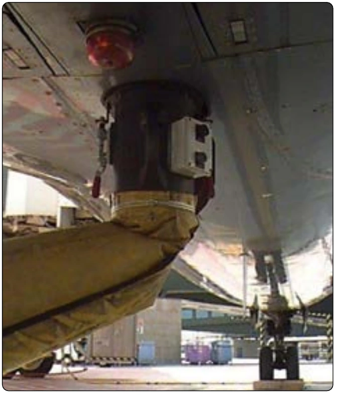
The air cycle air conditioning system is supplied with air by the aircraft pneumatic system. In turn, the pneumatic system is supplied by bleed air tap-offs on each engine compressor section or from the APU pneumatic supply. An external pneumatic air supply source may also be connected while the aircraft is stationary on the ground. In normal flight operations, a pneumatic manifold is supplied by the engine bleed air through the use of valves, regulators, and ducting. The air conditioning packs are supplied by this manifold as are other critical airframe systems, such as the anti-ice and hydraulic pressurization system.
Component Operation
Pack Valve
The pack valve is the valve that regulates bleed air from the pneumatic manifold into the air cycle air conditioning system. It is controlled with a switch from the air conditioning panel in the flight deck. Many pack valves are electrically controlled and pneumatically operated. Also known as the supply shutoff valve, the pack valve opens, closes, and modulates to allow the air cycle air conditioning system to be supplied with a designed volume of hot, pressurized air. [Figure 16-64] When an overheat or other abnormal condition requires that the air conditioning package be shut down, a signal is sent to the pack valve to close.
Bleed Air Bypass
A means for bypassing some of the pneumatic air supplied to the air cycle air conditioning system around the system is present on all aircraft. This warm bypassed air must be mixed with the cold air produced by the air cycle system so the air delivered to the cabin is a comfortable temperature. In the system shown in Figure 16-58, this is accomplished by the mixing valve. It simultaneously controls the flow of bypassed air and air to be cooled to meet the requirements of the auto temperature controller. It can also be controlled manually with the cabin temperature selector in manual mode. Other air cycle systems may refer to the valve that controls the air bypassed around the air cycle cooling system as a temperature control valve, trim air pressure regulating valve, or something similar.
Primary Heat Exchanger
Generally, the warm air dedicated to pass through the air cycle system first passes through a primary heat exchanger. It acts similarly to the radiator in an automobile. A controlled flow of ram air is ducted over and through the exchanger, which reduces the temperature of the air inside the system. [Figure 16-65] A fan draws air through the ram air duct when the aircraft is on the ground so that the heat exchange is possible when the aircraft is stationary. In flight, ram air doors are modulated to increase or decrease ram air flow to the exchanger according to the position of the wing flaps. During slow flight, when the flaps are extended, the doors are open. At higher speeds, with the flaps retracted, the doors move toward the closed position reducing the amount of ram air to the exchanger. Similar operation is accomplished with a valve on smaller aircraft. [Figure 16-66]