
Chapter 16
Cabin Environmental Control Systems
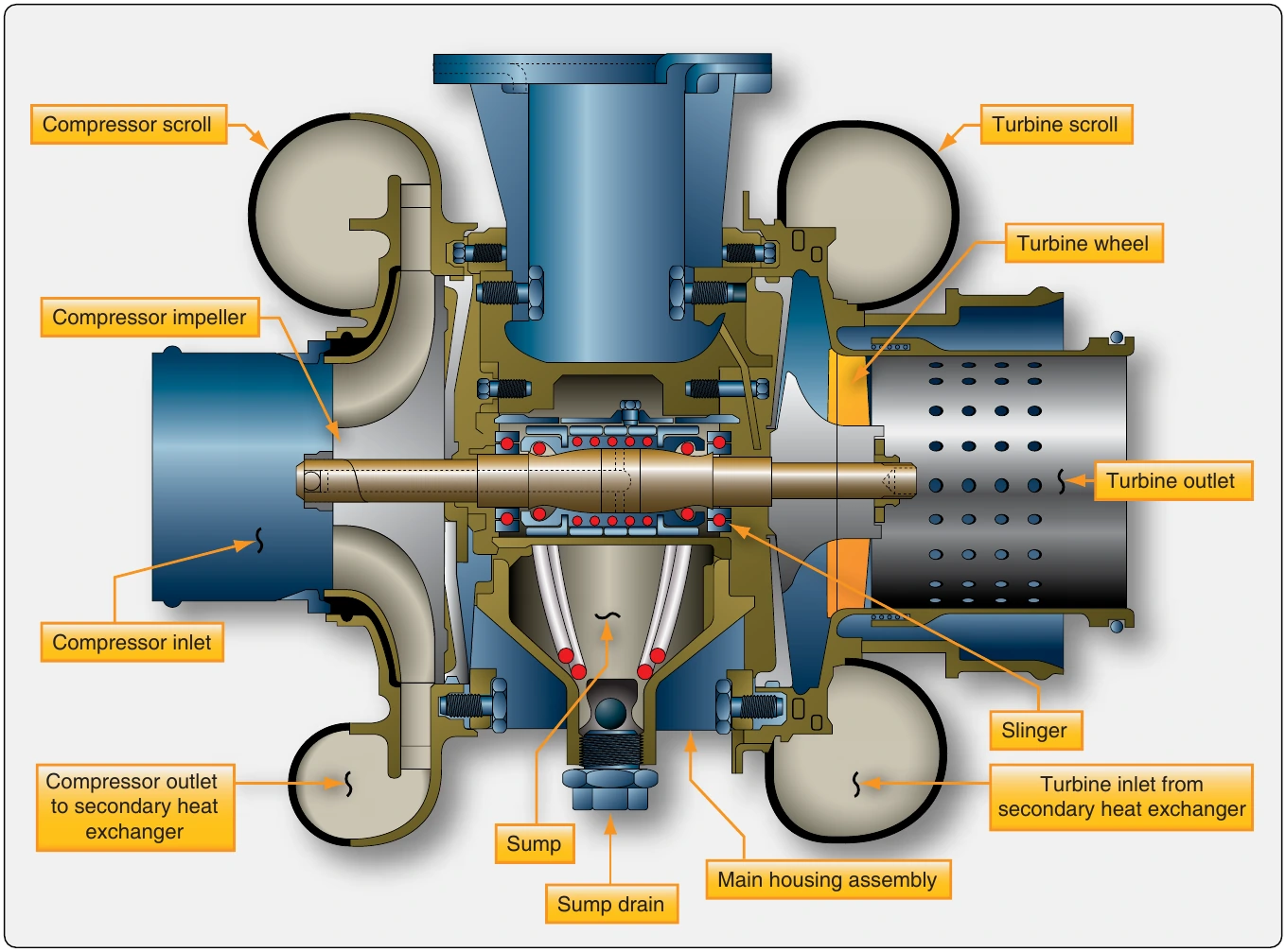
Refrigeration Turbine Unit or Air Cycle Machine & Secondary Heat Exchanger
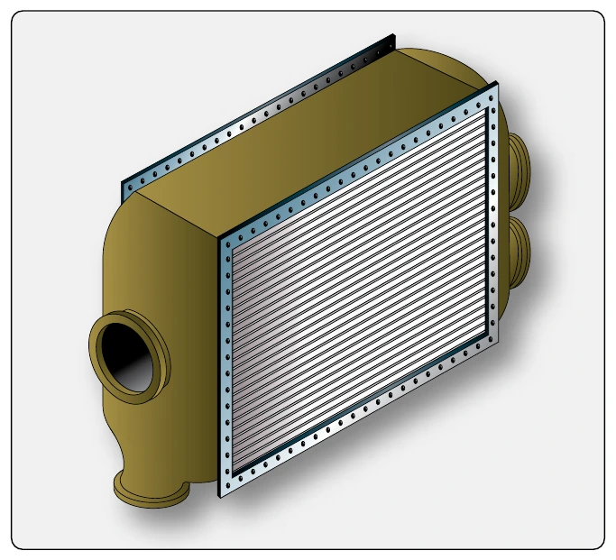
The heart of the air cycle air conditioning system is the refrigeration turbine unit, also known as the air cycle machine (ACM). It is comprised of a compressor that is driven by a turbine on a common shaft. System air flows from the primary heat exchanger into the compressor side of the ACM. As the air is compressed, its temperature rises. It is then sent to a secondary heat exchanger, similar to the primary heat exchanger located in the ram air duct. The elevated temperature of the ACM compressed air facilitates an easy exchange of heat energy to the ram air. The cooled system air, still under pressure from the continuous system air flow and the ACM compressor, exits the secondary heat exchanger. It is directed into the turbine side of the ACM. The steep blade pitch angle of the ACM turbine extracts more energy from the air as it passes through and drives the turbine. Once through, the air is allowed to expand at the ACM outlet, cooling even further. The combined energy loss from the air first driving the turbine and then expanding at the turbine outlet lowers the system air temperature to near freezing. [Figure 16-67]
Water Separator
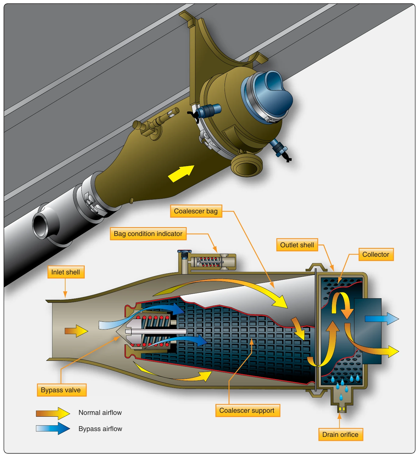
The cool air from the air cycle machine can no longer hold the quantity of water it could when it was warm. A water separator is used to remove the water from the saturated air before it is sent to the aircraft cabin. The separator operates with no moving parts. Foggy air from the ACM enters and is forced through a fiberglass sock that condenses and coalesces the mist into larger water drops. The convoluted interior structure of the separator swirls the air and water. The water collects on the sides of the separator and drains down and out of the unit, while the dry air passes through. A bypass valve is incorporated in case of a blockage. [Figure 16-68]
Refrigeration Bypass Valve
As mentioned, air exiting the ACM turbine expands and cools. It becomes so cold, it could freeze the water in the water separator, thus inhibiting or blocking airflow. A temperature sensor in the separator controls a refrigeration bypass valve designed to keep the air flowing through the water separator above freezing temperature. The valve is also identified by other names such as a temperature control valve, 35° valve, anti-ice valve, and similar. It bypasses warm air around the ACM when opened. The air is introduced into the expansion ducting, just upstream of the water separator, where it heats the air just enough to keep it from freezing. Thus, the refrigeration bypass valve regulates the temperature of the ACM discharge air so it does not freeze when passing through the water separator. This valve is visible in Figure 16-62 and is diagrammed in the system in Figure 16-63.
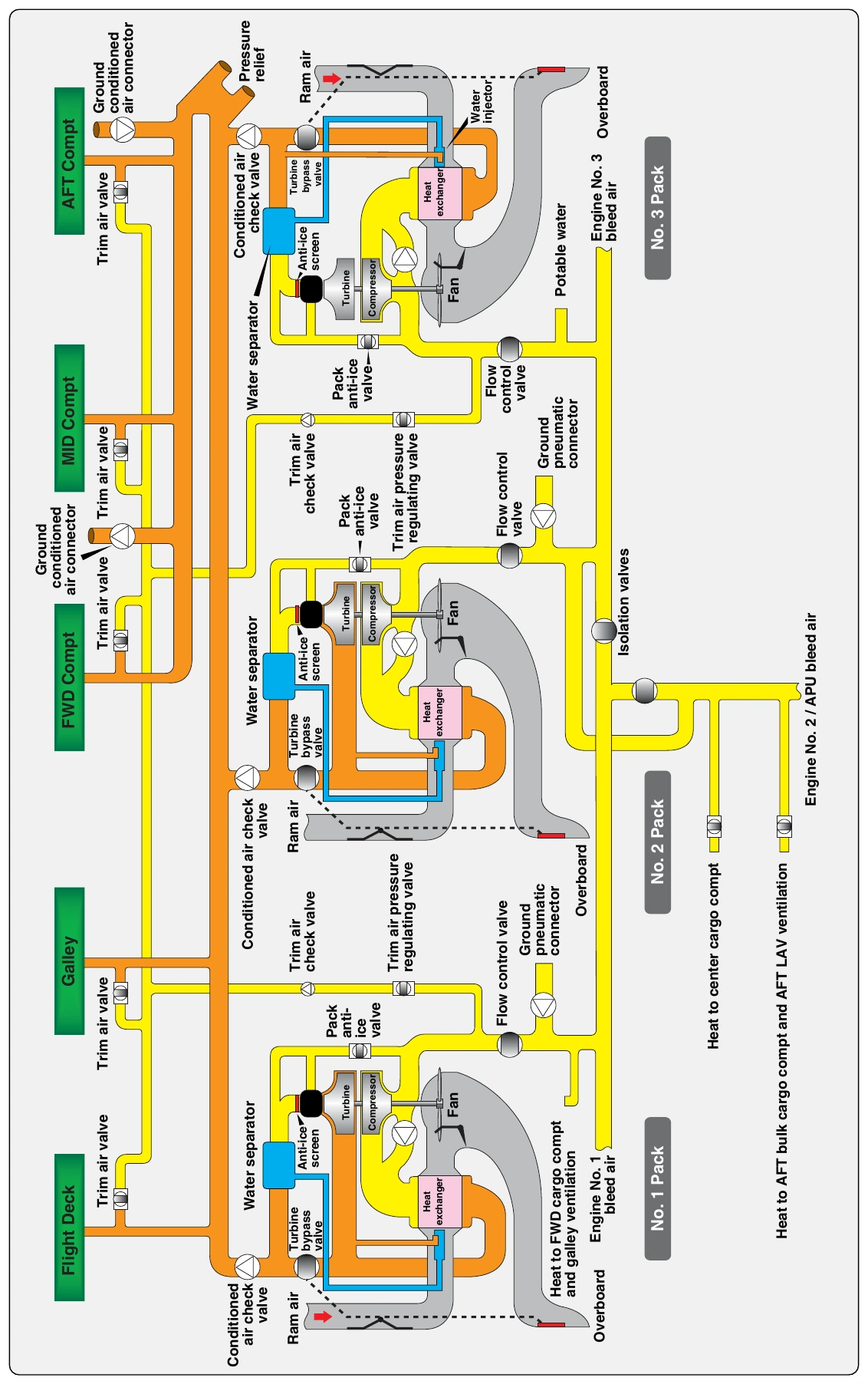
All air cycle air conditioning systems use at least one ram air heat exchanger and an air cycle machine with expansion turbine to remove heat energy from the bleed air, but variations exist. An example of a system different from that described above is found on the McDonnell Douglas DC-10. Bleed air from the pneumatic manifold is compressed by the air cycle machine compressor before it flows to a single heat exchanger. Condensed water from the water separator is sprayed into the ram air at its entrance to the exchanger to draw additional heat from the compressed bleed air as the water evaporates. A trim air valve for each cabin zone mixes bypassed bleed air with conditioned air in response to individual temperature selectors for each zone. When cooling air demands are low, a turbine bypass valve routes some heat exchanger air directly to the conditioned air manifold. [Figure 16-69]
Cabin Temperature Control System
Typical System Operation
Most cabin temperature control systems operate in a similar manner. Temperature is monitored in the cabin, flight deck, conditioned air ducts, and distribution air ducts. These values are input into a temperature controller, or temperature control regulator, normally located in the electronics bay. A temperature selector in the flight deck can be adjusted to input the desired temperature. [Figure 16-70] The temperature controller compares the actual temperature signals received from the various sensors with the desired temperature input. Circuit logic for the selected mode processes these input signals. An output signal is sent to a valve in the air cycle air conditioning system. This valve has different names depending on the aircraft manufacturer and design of the environmental control systems (i.e., mixing valve, temperature control valve, trim air valve). It mixes warm bleed air that bypassed the air cycle cooling process with the cold air produced by it. By modulating the valve in response to the signal from the temperature controller, air of the selected temperature is sent to the cabin through the air distribution system.
Cabin temperature pickup units and duct temperature sensors used in the temperature control system are thermistors. Their resistance changes as temperature changes. The temperature selector is a rheostat that varies its resistance as the knob is turned. In the temperature controller, resistances are compared in a bridge circuit. The bridge output feeds a temperature regulating function. An electric signal output is prepared and sent to the valve that mixes hot and cold air. On large aircraft with separate temperature zones, trim air modulating valves for each zone are used. The valves modulate to provide the correct mix required to match the selected temperature. Cabin, flight deck, and duct temperature sensors are strategically located to provide useful information to control cabin temperature. [Figure 16-71]
Vapor Cycle Air Conditioning
The absence of a bleed air source on reciprocating engine aircraft makes the use of an air cycle system impractical for conditioning cabin air. Vapor cycle air conditioning is used on most nonturbine aircraft that are equipped with air conditioning. However, it is not a source of pressurizing air as the air cycle system conditioned air is on turbine powered aircraft. The vapor cycle system only cools the cabin. If an aircraft equipped with a vapor cycle air conditioning system is pressurized, it uses one of the sources discussed in the pressurization section above. Vapor cycle air conditioning is a closed system used solely for the transfer of heat from inside the cabin to outside of the cabin. It can operate on the ground and in flight.