
Chapter 16
Cabin Environmental Control Systems
A negative pressure relief valve is included on pressurized aircraft to ensure that air pressure outside the aircraft does not exceed cabin air pressure. The spring-loaded relief valve opens inward to allow ambient air to enter the cabin when this situation arises. Too much negative pressure can cause difficulty when opening the cabin door. If high enough, it could cause structural damage since the pressure vessel is designed for cabin pressure to be greater than ambient.
Some aircraft are equipped with pressurization dump valves. These essentially are safety valves that are operated automatically or manually by a switch in the flight deck. They are used to quickly remove air and air pressure from the cabin, usually in an abnormal, maintenance, or emergency situation.
Incorporation of an emergency pressurization mode is found on some aircraft. A valve opens when the air conditioning packs fail or emergency pressurization is selected from the flight deck. It directs a mixture of bleed air and ram air into the cabin. This combines with fully closed outflow valves to preserve some pressurization in the aircraft.
Pressurization Gauges
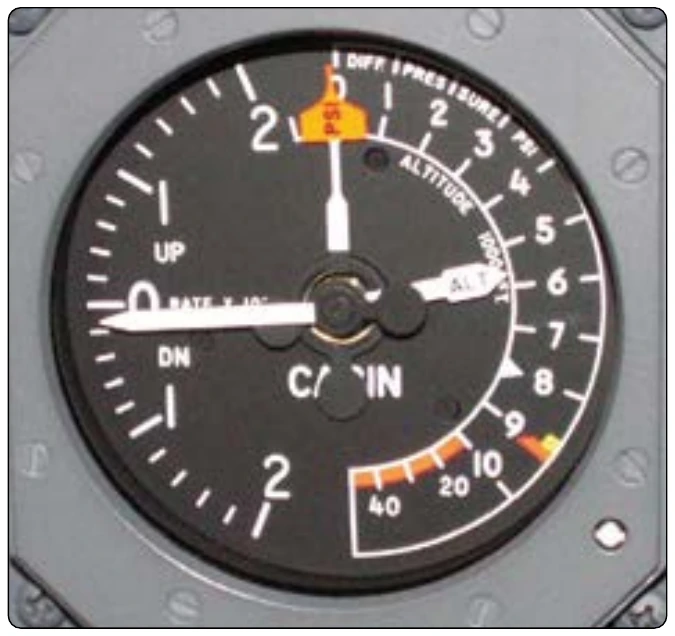
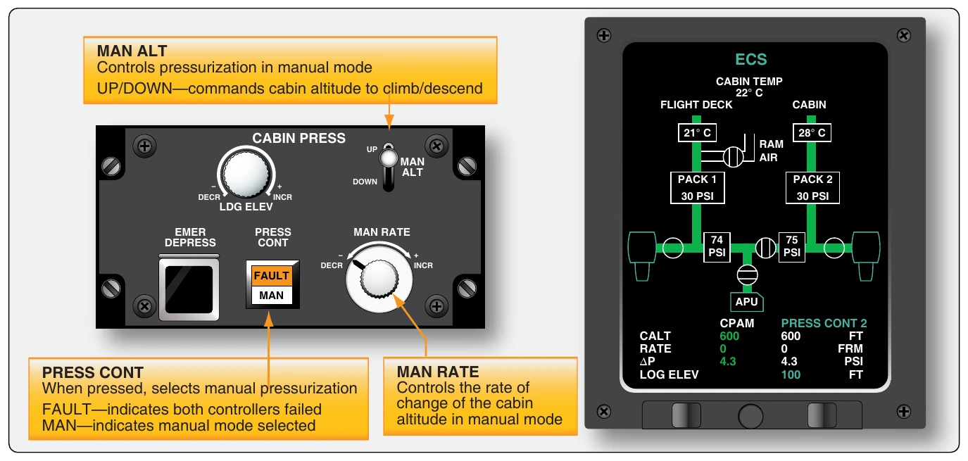
While all pressurization systems differ slightly, usually three flight deck indications, in concert with various warning lights and alerts, advise the crew of pressurization variables. They are the cabin altimeter, the cabin rate of climb or vertical speed indicator, and the cabin differential pressure indicator. These can be separate gauges or combined into one or two gauges. All are typically located on the pressurization panel, although sometimes they are elsewhere on the instrument panel. Outflow valve position indicator(s) are also common. [Figure 16-57] On modern aircraft equipped with digital aircraft monitoring systems with LCD displays, such as Engine Indicating and Crew Alerting System (EICAS) or Electronic Centralized Aircraft Monitor (ECAM), the pressurization panel may contain no gauges. The environmental control system (ECS) page of the monitoring system is selected to display similar information. Increased use of automatic redundancy and advanced operating logic simplifies operation of the pressurization system. It is almost completely automatic. The cabin pressurization panel remains in the flight deck primarily for manual control. [Figure 16-58]
Pressurization Operation
The normal mode of operation for most pressurization control systems is the automatic mode. A standby mode can also be selected. This also provides automatic control of pressurization, usually with different inputs, a standby controller, or standby outflow valve operation. A manual mode is available should the automatic and standby modes fail. This allows the crew to directly position the outflow valve through pneumatic or electric control, depending on the system.
Coordination of all pressurization components during various flight segments is essential. A weight-on-wheels (WOW) switch attached to the landing gear and a throttle position switch are integral parts of many pressurization control systems. Another name for the WOW switch is “squat” switch. During ground operations and prior to takeoff, the WOW switch typically controls the position of the pressurization safety valve, which is held in the open position until the aircraft takes off. In an advanced system, the WOW switch may give input to the pressurization controller, which in turn controls the positions and operation of all pressurization components. In other systems, the WOW switch may directly control the safety valve or a pneumatic source valve that causes the safety valve to be held open until the source is cut at takeoff when the WOW switch opens.
Throttle position switches can be used to cause a smooth transition from an unpressurized cabin to a pressurized cabin. A partial closing of the outflow valve(s) when the WOW switch is closed (on the ground) and the throttles are advanced gradually initiates pressurization during rollout. At takeoff, the rate of climb and the pressurization schedule require the outflow valve(s) to fully close. Passengers do not experience a harsh sensation from the fully closed valves because the cabin has already begun to pressurize slightly.
Once in flight, the pressurization controller automatically controls the sequence of operation of the pressurization components until the aircraft lands. When the WOW switch closes again at landing, it opens the safety valve(s) and, in some aircraft, the outflow valve(s) makes pressurizing impossible on the ground in the automatic pressurization mode. Maintenance testing of the system is done in manual mode. This allows the technician to control the position of all valves from the flight deck panel.
Air Distribution
Distribution of cabin air on pressurized aircraft is managed with a system of air ducts leading from the pressurization source into and throughout the cabin. Typically, air is ducted to and released from ceiling vents, where it circulates and flows out floor-level vents. The air then flows aft through the baggage compartments and under the floor area. It exits the pressure vessel through the outflow valve(s) mounted low, on, or near the aft pressure bulkhead. The flow of air is nearly imperceptible. Ducting is hidden below the cabin floor and behind walls and ceiling panels depending on the aircraft and system design. Valves to select pressurization air source, ventilating air, temperature trim air, as well as in line fans and jet pumps to increase flow in certain areas of the cabin, are all components of the air distribution system. Temperature sensors, overheat switches, and check valves are also common.
On turbine-powered aircraft, temperature-controlled air from the air conditioning system is the air that is used to pressurize the cabin. The final regulation of the temperature of that air is sometimes considered part of the distribution system. Mixing air-conditioned air with bleed air in a duct or a mixing chamber allows the crew to select the exact temperature desired for the cabin. The valve for mixing is controlled in the flight deck or cabin by a temperature selector. Centralized manifolds from which air can be distributed are common. [Figure 16-59]
Large aircraft may be divided into zones for air distribution. Each zone has its own temperature selector and associated valve to mix conditioned and bleed air so that each zone can be maintain at a temperature independent of the others.
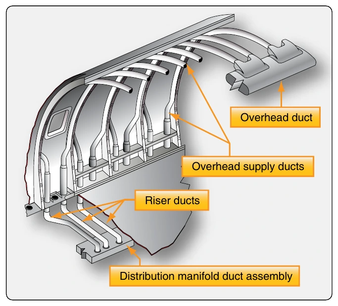
The air distribution system on most aircraft makes provisions for ducting and circulating cooling air to electronics equipment bays. It also contains a gasper air system. This is air ducted from the cold air manifold or duct to an overhead adjustable delivery nozzle at each passenger station. An inline fan controlled from the flight deck supplies a steady stream of gasper air that can be regulated or shut off with the delivery nozzle(s). [Figure 16-60]
When an aircraft is on the ground, operating the engines or the APU to provide air for air conditioning is expensive. It increases the time in service of these expensive components and expedites expensive mandatory overhauls that are performed at specified time intervals. Most high-performance, medium size, and larger turbine-powered aircraft are fitted with a receptacle in the air distribution system. To this a ground source of conditioned air can be connected via a ducting hose. The cabin can be heated or cooled through the aircraft’s air distribution ducting using air from the ground source. This limits the operating time on the engines andAPU. Once prefight checks and passenger boarding are completed, the ducting hose can be disconnected for taxi and flight. A check valve is used to prevent ground source air from flowing upstream into the air conditioning system. [Figure 16-61]