Chapter 16
Cabin Environmental Control Systems
Adjustments and settings on the pressure controller are the control input parameters for the cabin pressure regulator. The regulator controls the position of the outflow valve(s) normally located at the rear of the aircraft pressure vessel. Valve position determines the pressure level in the cabin.
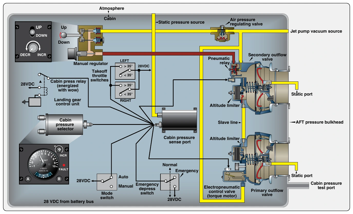
Modern aircraft often combine pneumatic, electric, and electronic control of pressurization. Cabin altitude, cabin rate of change, and barometric setting are made on the cabin pressure selector of the pressurization panel in the flight deck. Electric signals are sent from the selector to the cabin pressure controller, which functions as the pressure regulator. It is remotely located out of sight near the flight deck but inside the pressurized portion of the aircraft. The signals are converted from electric to digital and are used by the controller. Cabin pressure and ambient pressure are also input to the controller, as well as other inputs. [Figure 16-52]
Using this information, the controller, which is essentially a computer, supplies pressurization logic for various stages of a flight. On many small transport and business jets, the controller’s electric output signal drives a torque motor in the primary outflow valve. This modulates pneumatic airflow through the valve, which positions the valve to maintain the pressurization schedule.
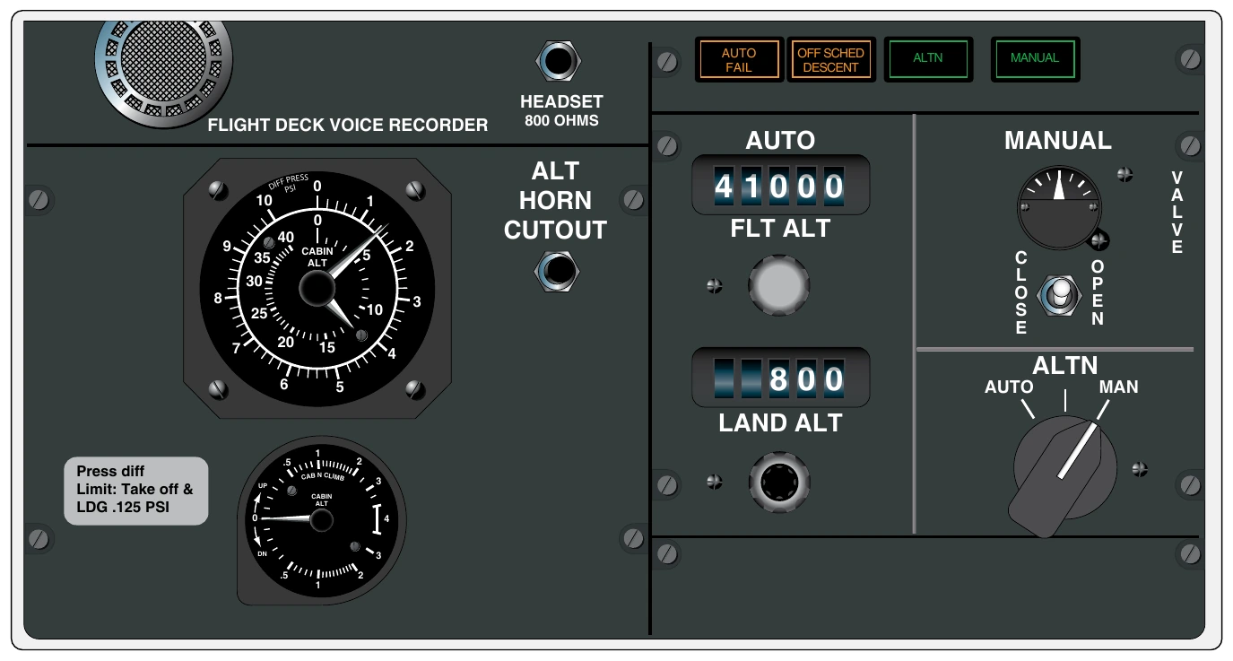
On many transport category aircraft, two cabin pressure controllers, or a single controller with redundant circuitry, are used. Located in the electronics equipment bay, they receive electric input from the panel selector, as well as ambient and cabin pressure input. Flight altitude and landing field altitude information are often the crew selection choices on the pressurization control panel. Cabin altitude, rate of climb, and barometric setting are automatic through built-in logic and communication with theADC and the flight management system (FMS). The controllers process the information and send electric signals to motors that directly position the outflow valve(s). [Figure 16-53]
Modern pressurization control is fully automatic once variable selections are made on the pressurization control panel if, in fact, there are any to be made. Entering or selecting a flight plan into the FMS of some aircraft automatically supplies the pressurization controller with the parameters needed to establish the pressurization schedule for the entire flight. No other input is needed from the crew.
All pressurization systems contain a manual mode that can override automatic control. This can be used in flight or on the ground during maintenance. The operator selects the manual mode on the pressurization control panel. A separate switch is used to position the outflow valve open or closed to control cabin pressure. The switch is visible in Figure 16-53, as well as a small gauge that indicates the position of the valve.
Cabin Air Pressure Regulator & Outflow Valve
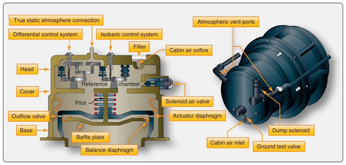
Controlling cabin pressurization is accomplished through regulating the amount of air that flows out of the cabin. A cabin outflow valve opens, closes, or modulates to establish the amount of air pressure maintained in the cabin. Some outflow valves contain the pressure regulating and the valve mechanism in a single unit. They operate pneumatically in response to the settings on the flight deck pressurization panel that influence the balance between cabin and ambient air pressure. [Figure 16-54]
Pneumatic operation of outflow valves is common. It is simple, reliable, and eliminates the need to convert air pressure operating variables into some other form. Diaphragms, springs, metered orifices, jet pumps, bellows, and poppet valves are used to sense and manipulate cabin and ambient air pressures to correctly position the outflow valve without the use of electricity. Outflow valves that combine the use of electricity with pneumatic operation have all-pneumatic standby and manual modes, as shown in Figure 16-52.
The pressure regulating mechanism can also be found as a separate unit. Many air transport category aircraft have an outflow valve that operates electrically, using signals sent from a remotely located cabin air pressure controller that acts as the pressure regulator. The controller positions the valve(s) to achieve the settings on the flight deck pressurization panel selectors according to predetermined pressurization schedules. Signals are sent to electric motors to move the valve as needed. On transports, often AC motors are used with a redundant DC motor for standby or manual operations. [Figure 16-55]
Cabin Air Pressure Safety Valve Operation
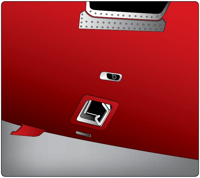
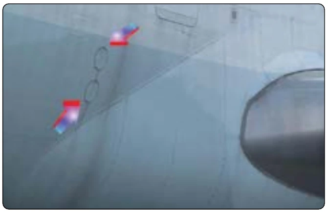
Aircraft pressurization systems incorporate various features to limit human and structural damage should the system malfunction or become inoperative. A means for preventing overpressurization is incorporated to ensure the structural integrity of the aircraft if control of the pressurization system is lost. A cabin air safety valve is a pressure relief valve set to open at a predetermined pressure differential. It allows air to flow from the cabin to prevent internal pressure from exceeding design limitations. Figure 16-56 shows cabin air pressure safety valves on a large transport category aircraft. On most aircraft, safety valves are set to open between 8 and 10 psid.
Pressurization safety valves are used to prevent the over pressurization of the aircraft cabin. They open at a preset differential pressure and allow air to flow out of the cabin. Wide-body transport category aircraft cabins may have more than one cabin pressurization safety valve.
Some outflow valves incorporate the safety valve function into their design. This is common on some corporate jets when two outflow valves are used. One outflow valve operates as the primary and the other as a secondary. Both contain a pilot valve that opens when the pressure differential increases to a preset value. This, in turn, opens the outflow valve(s) to prevent further pressurization. The outflow valves shown in Figure 16-52 operate in this manner.
Cabin altitude limiters are also used. These close the outflow valves when the pressure in the cabin drops well below the normal cabin altitude range, preventing a further increase in cabin altitude. Some limiter functions are built into the outflow valve(s). An example of this can be seen in that send input to the outflow valve or are part of the cabin pressurization controller logic.