
Chapter 16
Cabin Environmental Control Systems
R134a is a halogen compound (CF3CFH2). As mentioned, it has a boiling point of approximately –15 °F. It is not poisonous to inhale in small quantities, but it does displace oxygen. Suffocation is possible if breathed in mass quantity.
Regardless of manufacturer, refrigerants are sometimes called Freon®, which is a trade name owned by the Dupont Company. Caution should be used when handling any refrigerant. Because of the low boiling points, liquid refrigerants boil violently at typical atmospheric temperatures and pressure. They rapidly absorb heat energy from all surrounding matter. If a drop lands on skin, it freezes, resulting in a burn. Similar tissue damage can result if a drop gets in one’s eye. Gloves and other skin protection, as well as safety goggles, are required when working with refrigerant.
Receiver Dryer
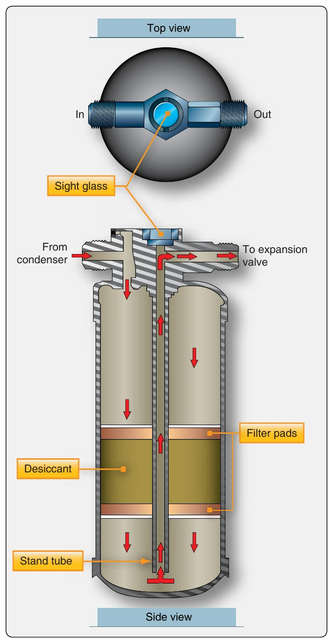
The receiver dryer acts as the reservoir of the vapor cycle system. It is located downstream of the condenser and upstream of the expansion valve. When it is very hot, more refrigerant is used by the system than when temperatures are moderate. Extra refrigerant is stored in the receiver dryer for this purpose.
Liquid refrigerant from the condenser flows into the receiver dryer. Inside, it passes through filters and a desiccant material. The filters remove any foreign particles that might be in the system. The desiccant captures any water in the refrigerant. Water in the refrigerant causes two major problems. First, the refrigerant and water combine to form an acid. If left in contact with the inside of the components and tubing, the acid deteriorates the materials from which these are made. The second problem with water is that it could form ice and block the flow of refrigerant around the system, rendering it inoperative. Ice is particularly a problem if it forms at the orifice in the expansion valve, which is the coldest point in the cycle.
Occasionally, vapor may find its way into the receiver dryer, such as when the gaseous refrigerant does not completely change state to a liquid in the condenser. A stand tube is used to remove refrigerant from the receiver dryer. It runs to the bottom of the unit to ensure liquid is withdrawn and forwarded to the expansion valve. At the top of the stand tube, a sight glass allows the technician to see the refrigerant. When enough refrigerant is present in the system, liquid flows in the sight glass. If low on refrigerant, any vapor present in the receiver dryer may be sucked up the stand tube causing bubbles to be visible in the sight glass. Therefore, bubbles in the sight glass indicate that the system needs to have more refrigerant added. [Figure 16-76]
Expansion Valve
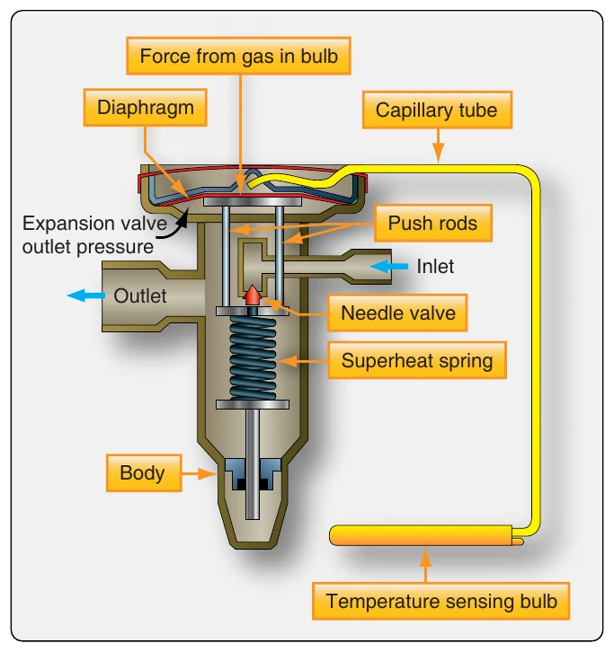
Refrigerant exits the receiver dryer and flows to the expansion valve. The thermostatic expansion valve has an adjustable orifice through which the correct amount of refrigerant is metered to obtain optimal cooling. This is accomplished by monitoring the temperature of the gaseous refrigerant at the outlet of the next component in the cycle, the evaporator. Ideally, the expansion valve should only let the amount of refrigerant spray into the evaporator that can be completely converted to a vapor.
The temperature of the cabin air to be cooled determines the amount of refrigerant the expansion valve should spray into the evaporator. Only so much is needed to completely change the state of the refrigerant from a liquid to a vapor. Too little causes the gaseous refrigerant to be superheated by the time it exits the evaporator. This is inefficient. Changing the state of the refrigerant from liquid to vapor absorbs much more heat than adding heat to already converted vapor (superheat). The cabin air blowing over the evaporator will not be cooled sufficiently if superheated vapor is flowing through the evaporator. If too much refrigerant is released by the expansion valve into the evaporator, some of it remains liquid when it exits the evaporator. Since it next flows to the compressor, this could be dangerous. The compressor is designed to compress only vapor. If liquid is drawn in and attempts are made to compress it, the compressor could break, since liquids are essentially incompressible.
The temperature of superheated vapor is higher than liquid refrigerant that has not totally vaporized. A coiled capillary tube with a volatile substance inside is located at the evaporator outlet to sense this difference. Its internal pressure increases and decreases as temperature changes. The coiled end of the tube is closed and attached to the evaporator outlet. The other end terminates in the area above a pressure diaphragm in the expansion valve. When superheated refrigerant vapor reaches the coiled end of the tube, its elevated temperature increases the pressure inside the tube and in the space above the diaphragm. This increase in pressure causes the diaphragm to overcome spring tension in the valve. It positions a needle valve that increases the amount of refrigerant released by the valve. The quantity of refrigerant is increased so that the refrigerant only just evaporates, and the refrigerant vapor does not superheat.
When too much liquid refrigerant is released by the expansion valve, low-temperature liquid refrigerant arrives at the inlet of the evaporator. The result is low pressure inside the temperature bulb and above the expansion valve diaphragm. The superheat spring in the valve moves the needle valve toward the closed position, reducing the flow of refrigerant into the evaporator as the spring overcomes the lower pressure above the diaphragm. [Figure 16-77]
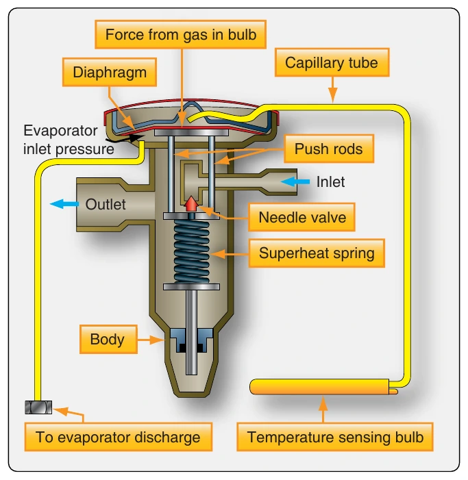
Vapor cycle air conditioning systems that have large evaporators experience significant pressure drops while refrigerant is flowing through them. Externally equalized expansion valves use a pressure tap from the outlet of the evaporator to help the superheat spring balance the diaphragm. This type of expansion valve is easily recognizable by the additional small-diameter line that comes from the evaporator into the valve (2 total). Better control of the proper amount of refrigerant allowed through the valve is attained by considering both the temperature and pressure of the evaporator refrigerant. [Figure 16-78]
Evaporator
Most evaporators are constructed of copper or aluminum tubing coiled into a compact unit. Fins are attached to increase surface area, facilitating rapid heat transfer between the cabin air blown over the outside of the evaporator with a fan and the refrigerant inside. The expansion valve, located at the evaporator inlet, changes the high pressure, high temperature refrigerant into low pressure, low temperature refrigerant which continues on into the evaporator. As the refrigerant absorbs heat from the cabin air, it changes into a low-pressure vapor. This is discharged from the evaporator outlet to the next component in the vapor cycle system, the compressor. The temperature and pressure pickups that regulate the expansion valve are located at the evaporator outlet.
The evaporator is situated in such a way that cabin air is pulled to it by a fan. The fan blows the air over the evaporator and discharges the cooled air back into the cabin. [Figure 16-79] This discharge can be direct when the evaporator is located in a cabin wall. A remotely located evaporator may require ducting from the cabin to the evaporator and from the evaporator back into the cabin. Sometimes the cool air produced may be introduced into an air distribution system where it can blow directly on the occupants through individual delivery vents. In this manner, the entire vapor cycle air conditioning system may be located fore or aft of the cabin. A multiposition fan switch controlled by the pilot is usually available. Figure 16-80 diagrams the vapor cycle air conditioning system in a Cessna Mustang very light jet. It has two evaporators that share in the cooling, with outlets integrated into a distribution system and flight deck mounted switches for the fans, as well as engaging and disengaging the system.
When cabin air is cooled by flowing over the evaporator, it can no longer retain the water that it could at higher temperature. As a result, it condenses on the outside of the evaporator and needs to be collected and drained overboard. Pressurized aircraft may contain a valve in the evaporator drain line that opens only periodically to discharge the water, to maintain pressurization. Fins on the evaporator must be kept from being damaged, which could inhibit airflow. The continuous movement of warm cabin air around the fins keeps condensed water from freezing. Ice on the evaporator reduces the efficiency of the heat exchange to the refrigerant.