
Chapter 16
Cabin Environmental Control Systems
Special servicing equipment is used to service vapor cycle air conditioning systems. The U.S. Environmental Protection Agency (EPA) has declared it illegal to release R12 refrigerant into the atmosphere. Equipment has been designed to capture the refrigerant during the servicing process. Although R134a does not have this restriction, it is illegal in some locations to release it to the atmosphere, and it may become universally so in the near future. It is good to waste them or to harm the environment by releasing them into the atmosphere. Capturing the refrigerant is a simple process designed into the proper servicing equipment. The technician should always be vigilant to use the approved refrigerant for the system being serviced and should follow all manufacturer’s instruction.
Manifold Set, Gauges, Hoses, & Fittings
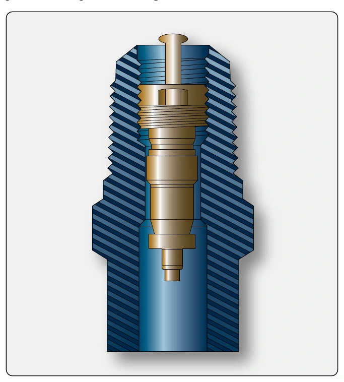
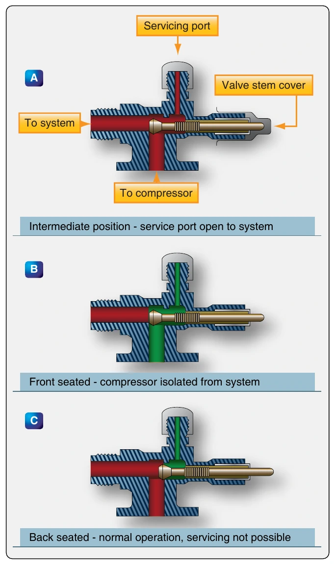
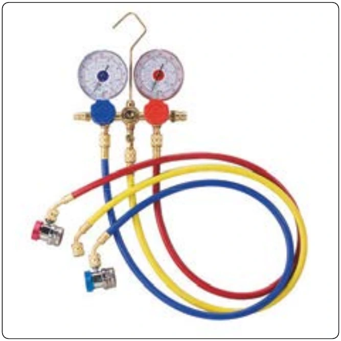
In the past, the main servicing device for vapor cycle air conditioning systems was the manifold set. It contains three hose fittings, two O-ring sealed valves, and two gauges. It is essentially a manifold into which the gauges, fittings, and valves are attached. The valves are positioned to connect or isolate the center hose with either fitting.
Hoses attach to the right and left manifold set fittings and the other ends of those hoses attach to the service valves in the vapor cycle system. The center fitting also has a hose attached to it. The other end of this hose connects to either a refrigerant supply or a vacuum pump, depending on the servicing function to be performed. All servicing operations are performed by manipulating the valves. [Figure 16-86]
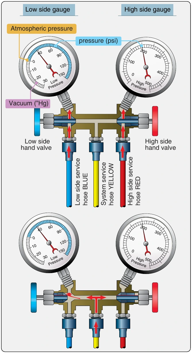
The gauges on the manifold set are dedicated—one for the low side of the system and the other for the high side. The low-pressure gauge is a compound gauge that indicates pressures above or below atmospheric pressure (0-gauge pressure). Below atmospheric pressure, the gauge is scaled in inches of mercury down to 30 inches. This is to indicate a vacuum. 29.92 inches of mercury equals an absolute vacuum (absolute zero air pressure). Above atmospheric pressure, gauge pressure is read in psi. The scale typically ranges from 0 to 60 psi, although some gauges extend up to 150 psi. The high-pressure gauge usually has a range from zero up to about 500 psi gauge pressure. It does not indicate vacuum (pressure lower than atmospheric). These gauges and their scales can be seen in Figure 16-87.
The low-pressure gauge is connected on the manifold directly to the low side fitting. The high-pressure gauge connects directly to the high side fitting. The center fitting of the manifold can be isolated from either of the gauges or the high and low service fittings by the hand valves. When these valves are turned fully clockwise, the center fitting is isolated. If the low-pressure valve is opened (turned counterclockwise), the center fitting is opened to the low-pressure gauge and the low side service line. The same is true for the high side when the high-pressure valve is opened. [Figure 16-87] Special hoses are attached to the fittings of the manifold valve for servicing the system. The high-pressure charging hose is usually red and attaches to the service valve located in the high side of the system. The low-pressure hose, usually blue, attaches to the service valve that is located in the low side of the system. The center hose attaches to the vacuum pump for evacuating the system, or to the refrigerant supply for charging the system. Proper charging hoses for the refrigerant specific service valves must be used. When not using the manifold set, be sure the hoses are capped to prevent moisture from contaminating the valves.
Full Service Refrigerant Recovery, Recycling, Evacuation, & Recharging Units
Regulations that require capture of all vapor cycle refrigerant have limited the use of the manifold set. It can still be used to charge a system. The refrigerant container is attached to the center hose and the manifold set valves are manipulated to allow flow into the low or high side of the system as required. But, emptying a system of refrigerant requires a service unit made to collect it. Allowing the refrigerant to flow into a collection container attached to the center hose will not capture the entire refrigerant charge, as the system and container pressures equalize above atmospheric pressure. An independent compressor and collection system is required.
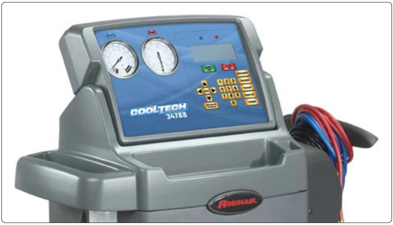
Modern refrigeration recharging and recovery units are available to perform all of the servicing functions required for vapor cycle air conditioning systems. These all-in-one service carts have the manifold set built into the unit. As such, the logic for using a manifold set still applies. Integral solenoid valves, reservoirs, filters, and smart controls allow the entire servicing procedure to be controlled from the unit panel once the high side and low side services hoses are connected. A built-in compressor enables complete system refrigerant purging. A built-in vacuum pump performs system evacuation. A container and recycling filters for the refrigerant and the lubricating oil allow total recovery and recycling of these fluids. The pressure gauges used on the service unit panel are the same as those on a manifold set. Top-of-the-line units have an automatic function that performs all of the servicing functions sequentially and automatically once the hoses are hooked up to the vapor cycle air conditioning system and the system quantity of refrigerant has been entered. [Figure 16-88]
Refrigerant Source
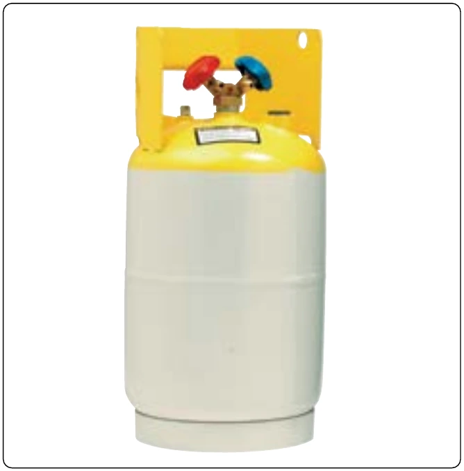
R134a comes in containers measured by the weight of the refrigerant they hold. Small 12-ounce to 21⁄2-pound cans are common for adding refrigerant. Larger 30- and 50-pound cylinders equipped with shutoff valves are often used to charge an evacuated system, and they are used in shops that service vapor cycle systems frequently. [Figure 16-89] These larger cylinders are also used in the full servicing carts described above. The amount of refrigerant required for any system is measured in pounds. Check the manufacturer’s service data and charge the system to the level specified using only the approved refrigerant from a known source.
Vacuum Pumps
Vacuum pumps used with a manifold set, or as part of a service cart, are connected to the vapor cycle system so that the system pressure can be reduced to a near total vacuum. The reason for doing this is to remove all of the water in the system. As mentioned, water can freeze, causing system malfunction and can also combine with the refrigerant to create corrosive compounds.
Once the system has been purged of its refrigerant and it is at atmospheric pressure, the vacuum pump is operated. It gradually reduces the pressure in the system. As it does, the boiling point of any water in the system is also reduced. Water boils off or is vaporized under the reduced pressure and is pulled from the system by the pump, leaving the system moisture free to be recharged with refrigerant. [Figure 16-90] The strength and efficiency of vacuum pumps varies as does the amount of time to hold the system at reduced pressure specified by manufacturers. Generally, the best-established vacuum is held for 15–30 minutes to ensure all water is removed from the system. Follow the manufacturer’s instructions when evacuating a vapor cycle air conditioning system. [Figure 16-91]