Chapter 16
Cabin Environmental Control Systems
Compressor
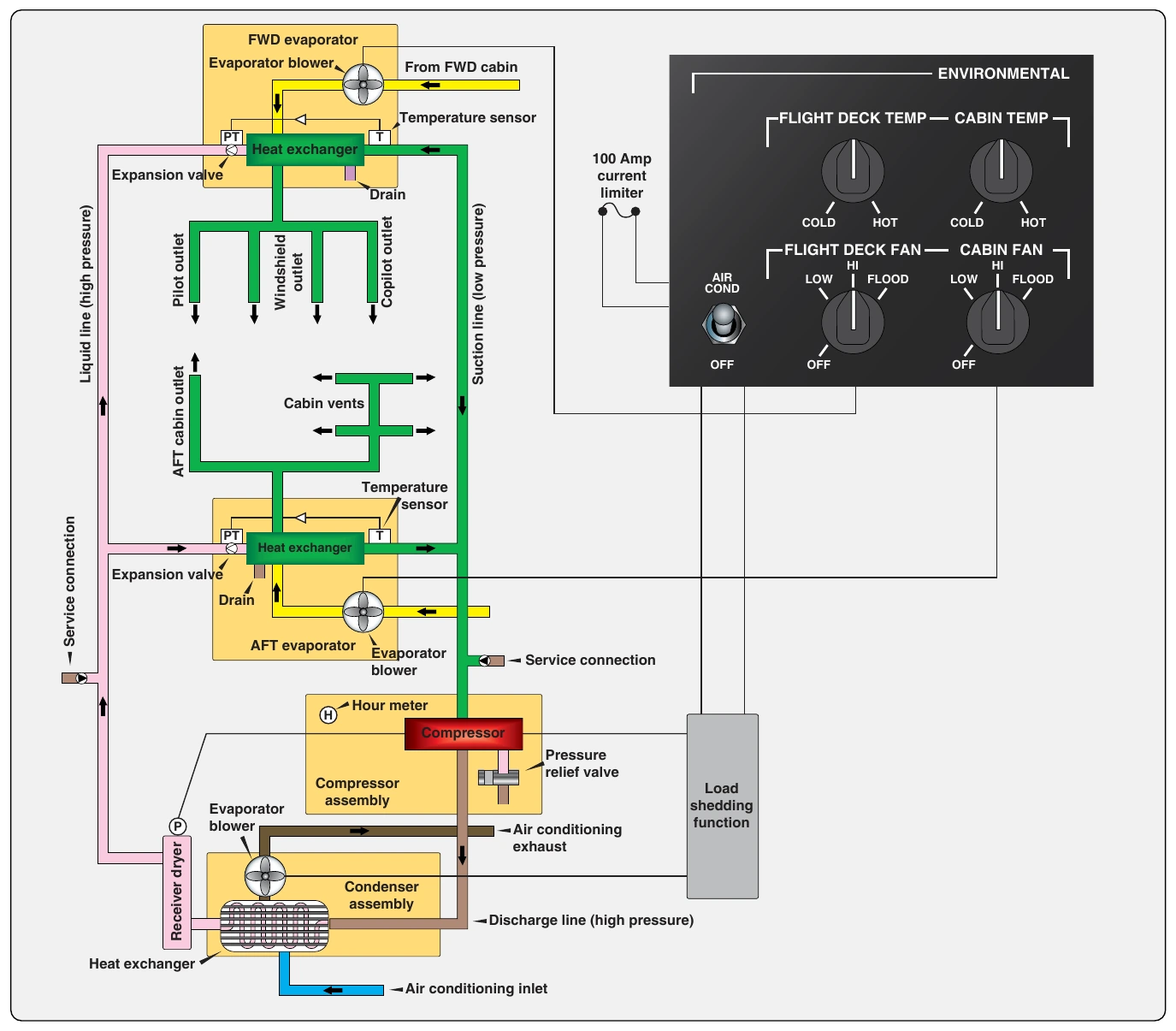
The compressor is the heart of the vapor cycle air conditioning system. It circulates the refrigerant around the vapor cycle system. It receives low-pressure, low-temperature refrigerant vapor from the outlet of the evaporator and compresses it. As the pressure is increased, the temperature also increases. The refrigerant temperature is raised above that of the outside air temperature. The refrigerant then flows out of the compressor to the condenser where it gives off the heat to the outside air.
The compressor is the dividing point between the low side and the high side of the vapor cycle system. Often it is incorporated with fittings or has fittings in the connecting lines to it that are designed to service the system with refrigerant. Access to the low and high sides of the system are required for servicing, which can be accomplished with fitting upstream and downstream of the compressor.
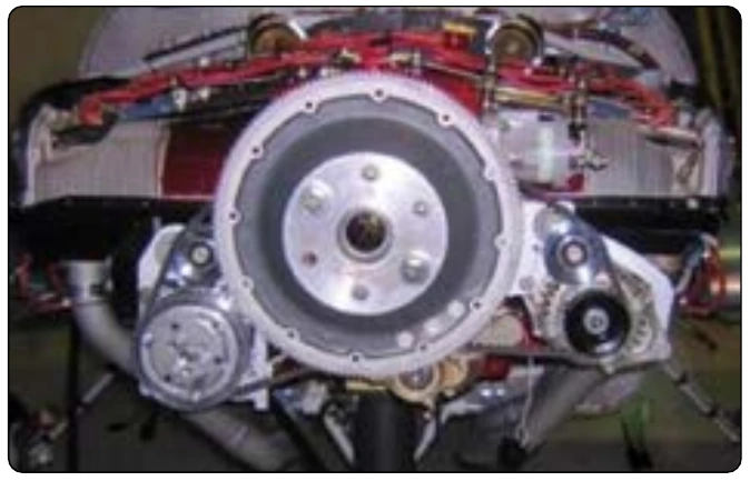
Modern compressors are either engine driven or driven by an electric motor. Occasionally, a hydraulically driven compressor is used. A typical engine-driven compressor, similar to that found in an automobile, is located in the engine nacelle and operated by a drive belt off of the engine crankshaft. An electromagnetic clutch engages when cooling is required, which causes the compressor to operate. When cooling is sufficient, power to the clutch is cut, and the drive pulley rotates but the compressor does not. [Figure 16-81]
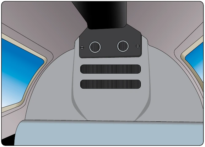
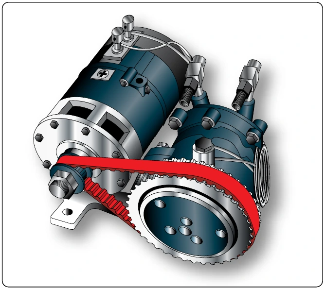
Dedicated electric motor-driven compressors are also used on aircraft. Use of an electric motor allows the compressor to be located nearly anywhere on the aircraft, since wires can be run from the appropriate bus to the control panel and to the compressor. [Figure 16-82] Hydraulically-driven compressors are also able to be remotely located. Hydraulic lines from the hydraulic manifold are run through a switch-activated solenoid to the compressor. The solenoid allows fluid to the compressor or bypasses it. This controls the operation of the hydraulically driven compressor.
Regardless of how the vapor cycle air conditioning compressor is driven, it is usually a piston type pump. It requires use of a lightweight oil to lubricate and seal the unit. The oil is entrained by the refrigerant and circulates with it around the system. The crankcase of the compressor retains a supply of the oil, the level of which can be checked and adjusted by the technician. Valves exist on some compressor installations that can be closed to isolate the compressor from the remainder of the vapor cycle system while oil servicing takes place.
Condenser
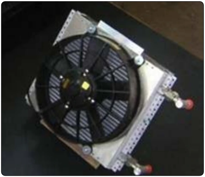
The condenser is the final component in the vapor cycle. It is a radiator-like heat exchanger situated so that outside air flows over it and absorbs heat from the high-pressure, high-temperature refrigerant received from the compressor. A fan is usually included to draw the air through the condenser during ground operation. On some aircraft, outside air is ducted to the condenser. On others, the condenser is lowered into the airstream from the fuselage via a hinged panel. Often, the panel is controlled by a switch on the throttle levers. It is set to retract the compressor and streamline the fuselage when full power is required. [Figure 16-83]
The outside air absorbs heat from the refrigerant flowing through the condenser. The heat loss causes the refrigerant to change state back into a liquid. The high-pressure liquid refrigerant then leaves the condenser and flows to the receiver dryer. A properly engineered system that is functioning normally fully condenses all the refrigerant flowing through the condenser.
Service Valves
All vapor cycle air conditioning systems are closed systems; however, access is required for servicing. This is accomplished through the use of two service valves. One valve is located in the high side of the system and the other in the low side. A common type of valve used on vapor cycle systems that operate with R12 refrigerant is the Schrader valve. It is similar to the valve used to inflate tires. [Figure 16-84] A central valve core seats and unseats by depressing a stem attached to it. A pin in the servicing hose fitting is designed to do this when screwed onto the valve’s exterior threads. All aircraft service valves should be capped when not in use.
R134a systems use valves that are very similar to the Schrader valve in function, operation, and location. As a safety device to prevent inadvertent mixing of refrigerants, R134a valve fittings are different from Schrader valve fittings and do not attach to Schrader valve threads. The R134a valve fittings are a quick-disconnect type.
Another type of valve called a compressor isolation valve is used on some aircraft. It serves two purposes. Like the Schrader valve, it permits servicing the system with refrigerant. It also can isolate the compressor so the oil level can be checked and replenished without opening the entire system and losing the refrigerant charge. These valves are usually hard mounted to the inlet and outlet of the compressor.
A compressor isolation valve has three positions. When fully open, it back seats and allows the normal flow of refrigerant in the vapor cycle. When fully closed or front seated, the valve isolates the compressor from the rest of the system and servicing with oil, or even replacement of the compressor, is possible without losing the refrigerant charge. When in an intermediate position, the valve allows access to the system for servicing. The system can be operated with the valve in this position but should be back seated for normal operation. The valve handle and service port should be capped when servicing is complete. [Figure 16-85]