
Chapter 17
Fire Protection Systems
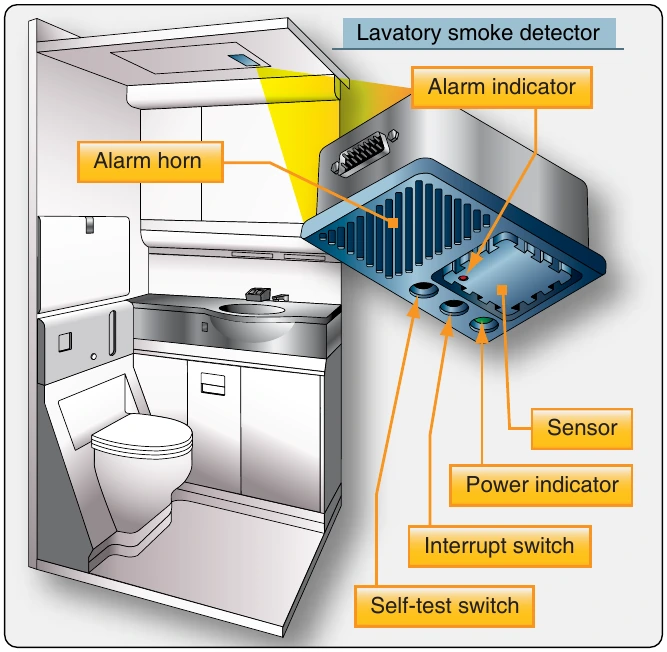
Airplanes that have a passenger capacity of 20 or more are equipped with a smoke detector system that monitors the lavatories for smoke. Smoke indications provide a warning light in the flight deck or provide a warning light or audible warning at the lavatory and at flight attendant stations that would be readily detected by a flight attendant. Each lavatory must have a built-in fire extinguisher that discharges automatically. The smoke detector is located in the ceiling of the lavatory. [Figure 17-22]
Lavatory Smoke Detector System
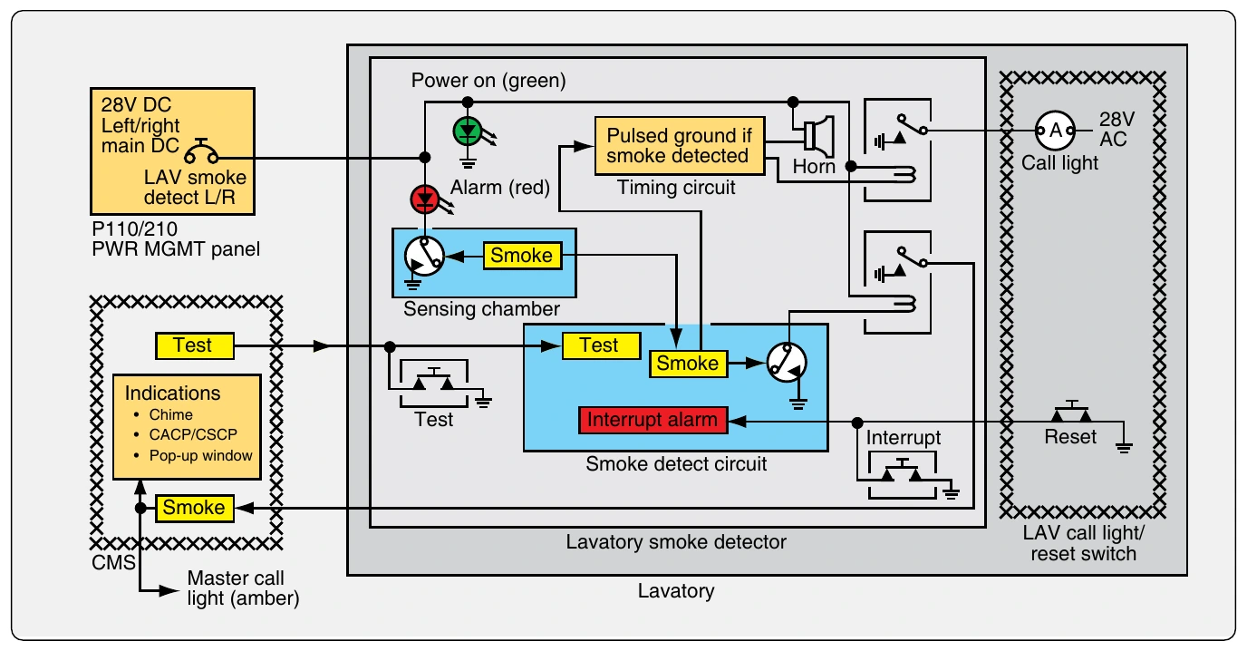
Refer to Figure 17-23. The lavatory smoke detector is powered by the 28-volt DC left/right main DC bus. If there is smoke in the sensing chamber of the smoke detector, the alarm LED (red) comes on. The timing circuit makes an intermittent ground. The warning horn and lavatory call light operate intermittently. The smoke detection circuit makes a ground for the relay. The energized relay makes a ground signal for the overhead electronics unit (OEU) in the central monitoring systems (CMS). This interface gives these indications: lavatory master call light flashes, cabin system control panel (CSCP) and cabin area control panel (CACP) pop-up window shows, and the lavatory call chime operates. Push the lavatory call reset switch or the smoke detector interrupt switch to cancel the smoke indications. If there is still smoke in the lavatory, the alarm LED (red) stays on. All smoke indications go away automatically when the smoke is gone.
Lavatory Fire Extinguisher System
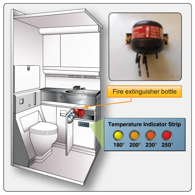
The lavatory compartment is outfitted with a fire extinguisher bottle to extinguish fires in the waste compartment. The fire extinguisher is a bottle with two nozzles. The bottle contains pressurized Halon 1301 or equivalent fire extinguishing agent. When the temperature in the waste compartment reaches approximately 170 °F, the solder that seals the nozzles melt and the Halon is discharged. Weighing the bottle is often the only way to determine if the bottle is empty or full. [Figure 17-24]
Fire Detection System Maintenance
Fire detector sensing elements are located in many high-activity areas around aircraft engines. Their location, together with their small size, increases the chance of damage to the sensing elements during maintenance. General maintenance of a fire detection system typically includes the inspection and servicing of damaged sections, containment of loose material that could short detector terminals, correcting connection joints and shielding, and replacement of damaged sensing elements. An inspection and maintenance program for all types of continuous-loop systems should include the following visual checks.
Sensing elements of a continuous-loop system should be inspected for the following:
- Cracked or broken sections caused by crushing or squeezing between inspection plates, cowl panels, or engine components.
- Abrasion caused by rubbing of the element on cowling, accessories, or structural members.
- Pieces of safety wire, or other metal particles, that may short the spot-detector terminals.
- Condition of rubber grommets in mounting clamps that may be softened from exposure to oils or hardened from excessive heat.
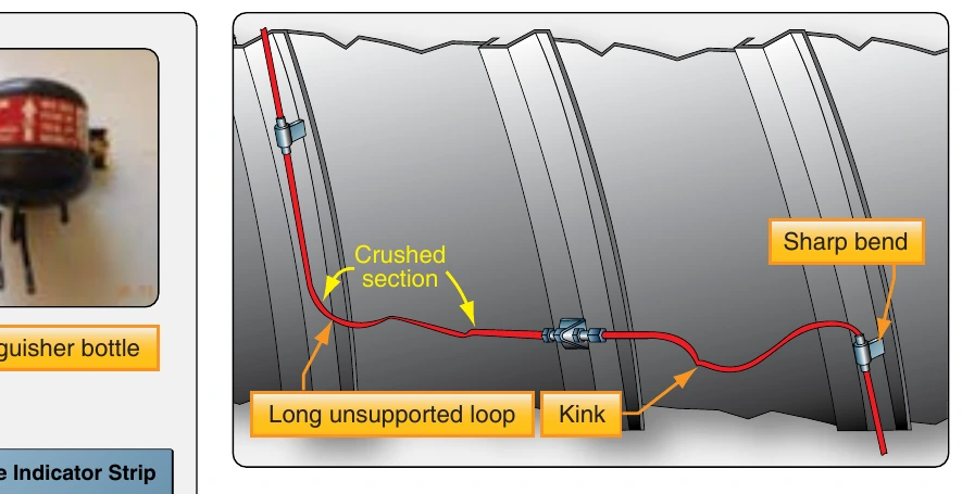
- Dents and kinks in sensing element sections. Limits on the element diameter, acceptable dents and kinks, and degree of smoothness of tubing contour are specified by manufacturers. No attempt should be made to straighten any acceptable dent or kink, since stresses may be set up that could cause tubing failure. [Figure 17-25]
- Nuts at the end of the sensing elements should be inspected for tightness and safety wire. [Figure 17-26] Loose nuts should be retorqued to the value specified by the manufacturer’s instructions. Some types of sensing element connection joints require the use of copper crush gaskets. These should be replaced any time a connection is separated.
- If shielded flexible leads are used, they should be inspected for fraying of the outer braid. The braided sheath is made up of many fine metal strands woven
into a protective covering surrounding the inner insulated wire. Continuous bending of the cable or rough treatment can break these fine wires, especially those near the connectors.
- Sensing element routing and clamping should be inspected carefully. [Figure 17-27] Long, unsupported sections may permit excessive vibration that can cause breakage. The distance between clamps on straight runs, usually about 8 to 10 inches, is specified by each manufacturer. At end connectors, the first support clamp usually is located about 4 to 6 inches from the end connector fittings. In most cases, a straight run of one inch is maintained from all connectors before a bend is started, and an optimum bend radius of 3 inches is normally adhered to.
- Interference between a cowl brace and a sensing element can cause rubbing. This interference may cause wear and short the sensing element.
- Grommets should be installed on the sensing element so that both ends are centered on its clamp. The split end of the grommet should face the outside of the nearest bend. Clamps and grommets should fit the element snugly. [Figure 17-28]
Fire Detection System Troubleshooting
The following troubleshooting procedures represent the most common difficulties encountered in engine fire detection systems:
- Intermittent alarms are most often caused by an intermittent short in the detector system wiring. Such shorts may be caused by a loose wire that occasionally touches a nearby terminal, a frayed wire brushing against a structure, or a sensing element rubbing against a structural member long enough to wear through the insulation. Intermittent faults often can be located by moving wires to recreate the short.