
Chapter 2
Aerodynamics, Aircraft Assembly, & Rigging
Rigging the helicopter coordinates the movements of the flight controls and establishes the relationship between the main rotor and its controls, and between the tail rotor and its controls. Rigging is not a difficult job, but it requires great precision and attention to detail. Strict adherence to rigging procedures described in the manufacturer’s maintenance manuals and service instructions is a must. Adjustments, clearances, and tolerances must be exact.
Rigging of the various flight control systems can be broken down into the following three major steps:
- Placing the control system in a specific position— holding it in position with pins, clamps, or jigs, then adjusting the various linkages to fit the immobilized control component.
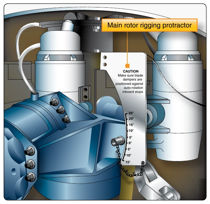
- Placing the control surfaces in a specific reference position—using a rigging jig, a precision bubble protractor, or a spirit level to check the angular difference between the control surface and some fixed surface on the aircraft. [Figure 2-23]
- Setting the maximum range of travel of the various components—this adjustment limits the physical movement of the control system.
After completion of the static rigging, a functional check of the flight control system must be accomplished. The nature of the functional check varies with the type of helicopter and system concerned, but usually includes determining that:
- The direction of movement of the main and tail rotor blades is correct in relation to movement of the pilot’s controls.
- The operation of interconnected control systems (engine throttle and collective pitch) is properly coordinated.
- The range of movement and neutral position of the pilot’s controls are correct.
- The maximum and minimum pitch angles of the main rotor blades are within specified limits. This includes checking the fore-and-aft and lateral cyclic pitch and collective pitch blade angles.
- The tracking of the main rotor blades is correct.
- In the case of multirotor aircraft, the rigging and movement of the rotor blades are synchronized.
- When tabs are provided on main rotor blades, they are correctly set.
- The neutral, maximum, and minimum pitch angles and coning angles of the tail rotor blades are correct.
- When dual controls are provided, they function correctly and in synchronization.
Upon completion of rigging, a thorough check should be made of all attaching, securing, and pivot points. All bolts, nuts, and rod ends should be properly secured and safetied as specified in the manufacturers’ maintenance and service instructions.
Configurations of Rotary-Wing Aircraft
Autogyro
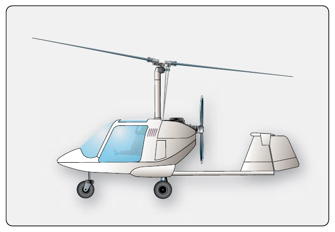
An autogyro is an aircraft with a free-spinning horizontal rotor that turns due to passage of air upward through the rotor. This air motion is created from forward motion of the aircraft resulting from either a tractor or pusher configured engine/propeller design. [Figure 2-24]
Single Rotor Helicopter
An aircraft with a single horizontal main rotor that provides both lift and direction of travel is a single rotor helicopter. A secondary rotor mounted vertically on the tail counteracts the rotational force (torque) of the main rotor to correct yaw of the fuselage. [Figure 2-25]
Dual Rotor Helicopter
An aircraft with two horizontal rotors that provide both the lift and directional control is a dual rotor helicopter. The rotors are counterrotating to balance the aerodynamic torque and eliminate the need for a separate antitorque system. [Figure 2-26]
Types of Rotor Systems
Fully Articulated Rotor
A fully articulated rotor is found on aircraft with more than two blades and allows movement of each individual blade in three directions. In this design, each blade can rotate about the pitch axis to change lift; each blade can move back and forth in plane, lead and lag; and flap up and down through a hinge independent of the other blades. [Figure 2-27]