
Chapter 2
Aerodynamics, Aircraft Assembly, & Rigging
Gyroscopic Forces
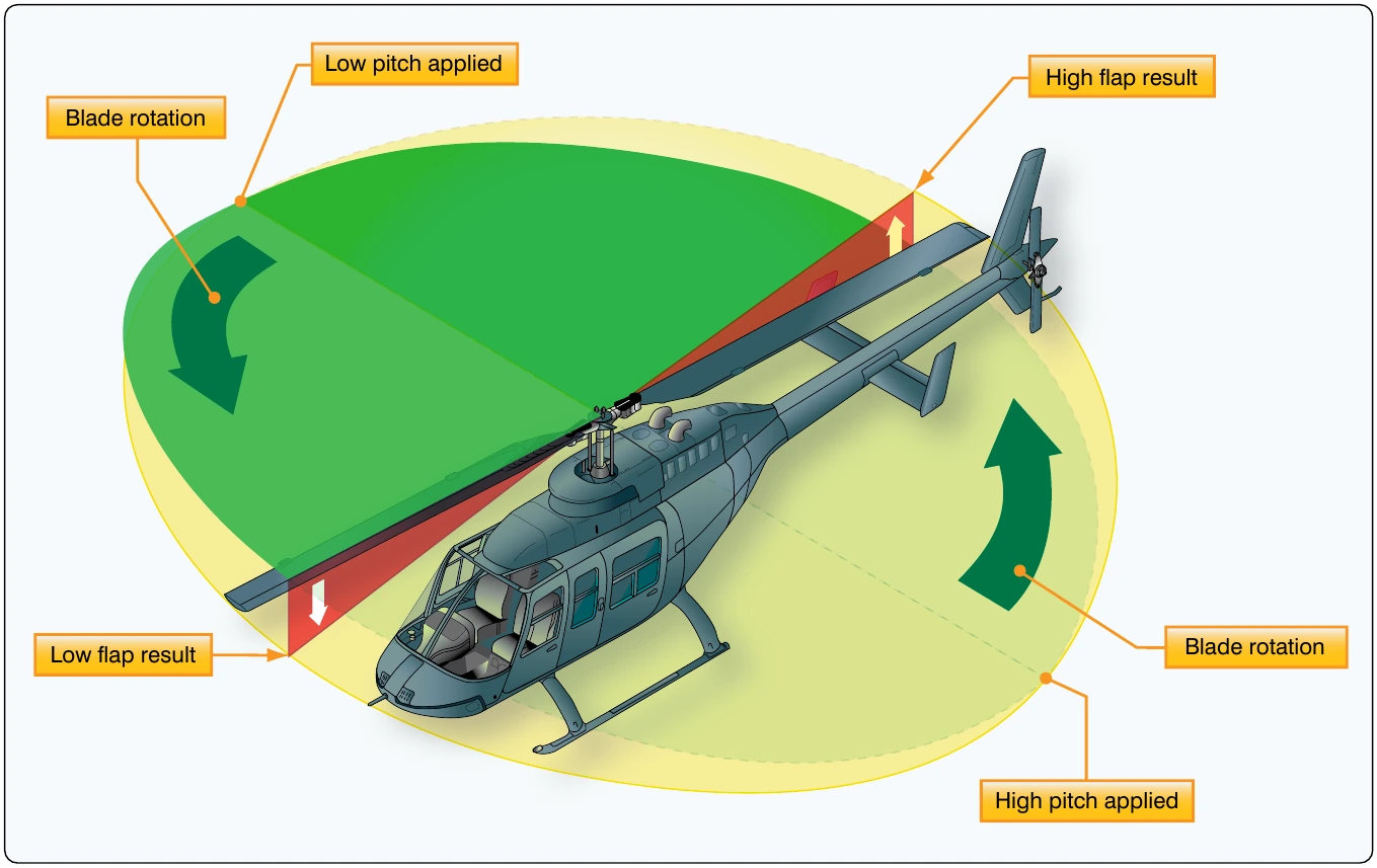
The spinning main rotor of a helicopter acts like a gyroscope. As such, it has the properties of gyroscopic action, one of which is precession. Gyroscopic precession is the resultant action or deflection of a spinning object when a force is applied to this object. This action occurs approximately 90° in the direction of rotation from the point where the force is applied. [Figure 2-29] Through the use of this principle, the tip-path plane of the main rotor may be tilted from the horizontal.
Examine a two-bladed rotor system to see how gyroscopic precession affects the movement of the tip-path plane. Moving the cyclic pitch control increases the AOA of one rotor blade with the result that a greater lifting force is applied at that point in the plane of rotation. This same control movement simultaneously decreases the AOA of the other blade the same amount, thus decreasing the lifting force applied at that point in the plane of rotation. The blade with the increased AOA tends to flap up; the blade with the decreased AOA tends to flap down. Because the rotor disc acts like a gyro, the blades reach maximum deflection at a point approximately 90° later in the plane of rotation. As shown in Figure 2-30, the retreating blade AOA is increased and the advancing blade AOA is decreased resulting in a tipping forward of the tip-path plane, since maximum deflection takes place 90° later when the blades are at the rear and front, respectively. In a rotor system using three or more blades, the movement of the cyclic pitch control changes the AOA of each blade an appropriate amount so that the end result is the same.
The movement of the cyclic pitch control in a two-bladed rotor system increases the AOA of one rotor blade with the result that a greater lifting force is applied at this point in the plane of rotation. This same control movement simultaneously decreases the AOA of the other blade a like amount, thus decreasing the lifting force applied at this point in the plane of rotation. The blade with the increased AOA tends to rise; the blade with the decreased AOA tends to lower. However, gyroscopic precession prevents the blades from rising or lowering to maximum deflection until a point approximately 90° later in the plane of rotation.
In a three-bladed rotor, the movement of the cyclic pitch control changes the AOA of each blade an appropriate amount so that the end result is the same, a tipping forward of the tip-path plane when the maximum change in AOA is made as each blade passes the same points at which the maximum increase and decrease are made for the two-bladed rotor as shown in Figure 2-30. As each blade passes the 90° position on the left, the maximum increase in AOA occurs. As each blade passes the 90° position to the right, the maximum decrease in AOA occurs. Maximum deflection takes place 90° later, maximum upward deflection at the rear and maximum downward deflection at the front; the tip-path plane tips forward.
Helicopter Flight Conditions
Hovering Flight
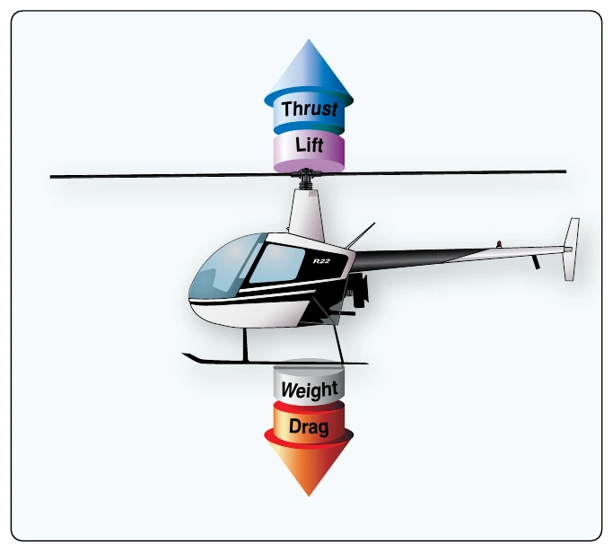
During hovering flight, a helicopter maintains a constant position over a selected point, usually a few feet above the ground. For a helicopter to hover, the lift and thrust produced by the rotor system act straight up and must equal the weight and drag, which act straight down. [Figure 2-31] While hovering, the amount of main rotor thrust can be changed to maintain the desired hovering altitude. This is done by changing the angle of incidence (by moving the collective) of the rotor blades and hence the AOA of the main rotor blades. Changing the AOA changes the drag on the rotor blades, and the power delivered by the engine must change as well to keep the rotor speed constant.
The weight that must be supported is the total weight of the helicopter and its occupants. If the amount of lift is greater than the actual weight, the helicopter accelerates upwards until the lift force equals the weight gain altitude; if thrust is less than weight, the helicopter accelerates downward. When operating near the ground, the effect of the closeness to the ground changes this response.
The drag of a hovering helicopter is mainly induced drag incurred while the blades are producing lift. There is, however, some profile drag on the blades as they rotate through the air. Throughout the rest of this discussion, the term drag includes both induced and profile drag.
An important consequence of producing thrust is torque. As discussed earlier, Newton’s third law states that for every action there is an equal and opposite reaction. Therefore, as the engine turns the main rotor system in a counterclockwise direction, the helicopter fuselage tends to turn clockwise. The amount of torque is directly related to the amount of engine power being used to turn the main rotor system. Remember, as power changes, torque changes.
To counteract this torque-induced turning tendency, an antitorque rotor or tail rotor is incorporated into most helicopter designs. A pilot can vary the amount of thrust produced by the tail rotor in relation to the amount of torque produced by the engine. As the engine supplies more power to the main rotor, the tail rotor must produce more thrust to overcome the increased torque effect. This is done through the use of antitorque pedals.
Translating Tendency or Drift
During hovering flight, a single main rotor helicopter tends to drift or move in the direction of tail rotor thrust. This drifting tendency is called translating tendency. [Figure 2-32]
To counteract this drift, one or more of the following features may be used. All examples are for a counterclockwise rotating main rotor system.
- The main transmission is mounted at a slight angle to the left (when viewed from behind) so that the rotor mast has a built-in tilt to oppose the tail rotor thrust.
- Flight controls can be rigged so that the rotor disc is tilted to the right slightly when the cyclic is centered. Whichever method is used, the tip-path plane is tilted slightly to the left in the hover.
- If the transmission is mounted so that the rotor shaft is vertical with respect to the fuselage, the helicopter “hangs” left skid low in the hover. The opposite is true for rotor systems turning clockwise when viewed from above.
- In forward flight, the tail rotor continues to push to the right, and the helicopter makes a small angle with the wind when the rotors are level and the slip ball is in the middle. This is called inherent sideslip.
Ground Effect
When hovering near the ground, a phenomenon known as ground effect takes place. This effect usually occurs at heights between the surface and approximately one rotor diameter above the surface. The friction of the ground causes the downwash from the rotor to move outwards from the helicopter. This changes the relative direction of the downwash from a purely vertical motion to a combination of vertical and horizontal motion. As the induced airflow through the rotor disc is reduced by the surface friction, the lift vector increases. This allows a lower rotor blade angle for the same amount of lift, which reduces induced drag. Ground effect also restricts the generation of blade tip vortices due to the downward and outward airflow making a larger portion of the blade produce lift. When the helicopter gains altitude vertically, with no forward airspeed, induced airflow is no longer restricted, and the blade tip vortices increase with the decrease in outward airflow. As a result, drag increases which means a higher pitch angle, and more power is needed to move the air down through the rotor.