
Chapter 2
Aerodynamics, Aircraft Assembly, & Rigging
Winglets
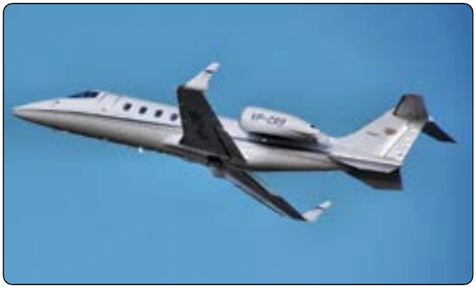
Winglets are the near-vertical extension of the wingtip that reduces the aerodynamic drag associated with vortices that develop at the wingtips as the airplane moves through the air. By reducing the induced drag at the tips of the wings, fuel consumption goes down and range is extended. Figure 2-17 shows an example of a Learjet 60 with winglets.
Canard Wings
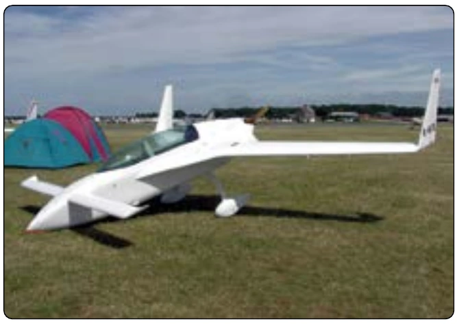
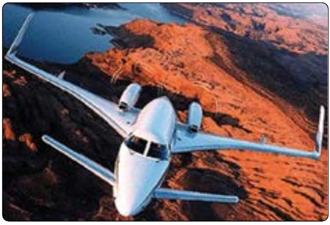
A canard wing aircraft is an airframe configuration of a fixed-wing aircraft in which a small wing or horizontal airfoil is ahead of the main lifting surfaces, rather than behind them as in a conventional aircraft. The canard may be fixed, movable, or designed with elevators. Good examples of aircraft with canard wings are the Rutan VariEze and Beechcraft 2000 Starship. [Figures 2-18 and 2-19]
Wing Fences
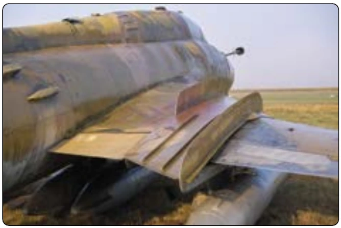
Wing fences are flat metal vertical plates fixed to the upper surface of the wing. They obstruct spanwise airflow along the wing, and prevent the entire wing from stalling at once. They are often attached on swept-wing aircraft to prevent the spanwise movement of air at high AOA. Their purpose is to provide better slow speed handling and stall characteristics. [Figure 2-20]
Control Systems for Large Aircraft
Mechanical Control
This is the basic type of system that was used to control early aircraft and is currently used in smaller aircraft where aerodynamic forces are not excessive. The controls are mechanical and manually operated.
The mechanical system of controlling an aircraft can include cables, push-pull tubes, and torque tubes. The cable system is the most widely used because deflections of the structure to which it is attached do not affect its operation. Some aircraft incorporate control systems that are a combination of all three. These systems incorporate cable assemblies, cable guides, linkage, adjustable stops, and control surface snubber or mechanical locking devices. These surface locking devices, usually referred to as a gust lock, limits the external wind forces from damaging the aircraft while it is parked or tied down.
Hydromechanical Control
As the size, complexity, and speed of aircraft increased, actuation of controls in flight became more difficult. It soon became apparent that the pilot needed assistance to overcome the aerodynamic forces to control aircraft movement. Spring tabs, which were operated by the conventional control system, were moved so that the airflow over them actually moved the primary control surface. This was sufficient for the aircraft operating in the lowest of the high speed ranges (250–300 mph). For higher speeds, a power-assisted (hydraulic) control system was designed.
Conventional cable or push-pull tube systems link the flight deck controls with the hydraulic system. With the system activated, the pilot’s movement of a control causes the mechanical link to open servo valves, thereby directing hydraulic fluid to actuators, which convert hydraulic pressure into control surface movements.
Because of the efficiency of the hydromechanical flight control system, the aerodynamic forces on the control surfaces cannot be felt by the pilot, and there is a risk of overstressing the structure of the aircraft. To overcome this problem, aircraft designers incorporated artificial feel systems into the design that provided increased resistance to the controls at higher speeds. Additionally, some aircraft with hydraulically powered control systems are fitted with a device called a stick shaker, which provides an artificial stall warning to the pilot.