
Chapter 2
Aerodynamics, Aircraft Assembly, & Rigging
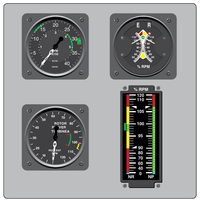
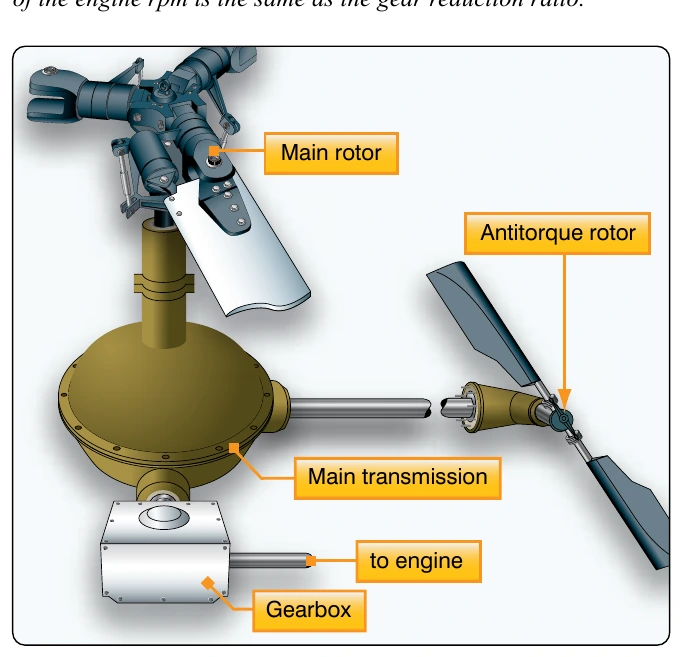
On free turbine engines, no clutch is required, as the gas producer turbine is essentially disconnected from the power turbine. When the engine is started, there is little resistance from the power turbine. This enables the gas producer turbine to accelerate to normal idle speed without the load of the transmission and rotor system dragging it down. As the gas pressure increases through the power turbine, the rotor blades begin to turn, slowly at first and then gradually accelerate to normal operating rpm.
On reciprocating helicopters, the two main types of clutches are the centrifugal clutch and the belt drive clutch.
Centrifugal Clutch
The centrifugal clutch is made up of an inner assembly and an outer drum. The inner assembly, which is connected to the engine driveshaft, consists of shoes lined with material similar to automotive brake linings. At low engine speeds, springs hold the shoes in, so there is no contact with the outer drum, which is attached to the transmission input shaft. As engine speed increases, centrifugal force causes the clutch shoes to move outward and begin sliding against the outer drum. The transmission input shaft begins to rotate, causing the rotor to turn, slowly at first, but increasing as the friction increases between the clutch shoes and transmission drum. As rotor speed increases, the rotor tachometer needle shows an increase by moving toward the engine tachometer needle. When the two needles are superimposed, the engine and the rotor are synchronized, indicating the clutch is fully engaged and there is no further slippage of the clutch shoes.
Belt Drive Clutch
Some helicopters utilize a belt drive to transmit power from the engine to the transmission. A belt drive consists of a lower pulley attached to the engine, an upper pulley attached to the transmission input shaft, a belt or a series of V-belts, and some means of applying tension to the belts. The belts fit loosely over the upper and lower pulley when there is no tension on the belts. This allows the engine to be started without any load from the transmission. Once the engine is running, tension on the belts is gradually increased. When the rotor and engine tachometer needles are superimposed, the rotor and the engine are synchronized, and the clutch is then fully engaged. Advantages of this system include vibration isolation, simple maintenance, and the ability to start and warm up the engine without engaging the rotor.
Freewheeling Unit
Since lift in a helicopter is provided by rotating airfoils, these airfoils must be free to rotate if the engine fails. The freewheeling unit automatically disengages the engine from the main rotor when engine rpm is less than main rotor rpm. This allows the main rotor and tail rotor to continue turning at normal in-flight speeds. The most common freewheeling unit assembly consists of a one-way sprag clutch located between the engine and main rotor transmission. This is usually in the upper pulley in a piston helicopter or mounted on the accessory gearbox in a turbine helicopter. When the engine is driving the rotor, inclined surfaces in the sprag clutch force rollers against an outer drum. This prevents the engine from exceeding transmission rpm. If the engine fails, the rollers move inward, allowing the outer drum to exceed the speed of the inner portion. The transmission can then exceed the speed of the engine. In this condition, engine speed is less than that of the drive system, and the helicopter is in an autorotative state.
Airplane Assembly & Rigging
The primary assembly of a type certificated aircraft is normally performed by the manufacturer at the factory. The assembly includes putting together the major components, such as the fuselage, empennage, wing sections, nacelles, landing gear, and installing the powerplant. Attached to the wing and empennage are primary flight control surfaces including ailerons, elevators, and rudder. Additionally, installation of auxiliary flight control surfaces may include wing flaps, spoilers, speed brakes, slats, and leading edge flaps.
The assembly of other aircraft outside of a manufacturer’s facility is usually limited to smaller size and experimental amateur-built aircraft. Typically, after a major overhaul, repair, or alteration, the reassembly of an aircraft may include reattaching wings to the fuselage, balancing of and installation of flight control surfaces, installation of the landing gear, and installation of the powerplant(s).
Rebalancing of Control Surfaces
This section is presented for familiarization purposes only. Explicit instructions for the balancing of control surfaces are given in the manufacturer’s service and overhaul manuals for the specific aircraft and must be followed closely.
Any time repairs on a control surface add weight fore or aft of the hinge center line, the control surface must be rebalanced. When an aircraft is repainted, the balance of the control surfaces must be checked. Any control surface that is out of balance is unstable and does not remain in a streamlined position during normal flight. For example, an aileron that is trailing edge heavy moves down when the wing deflects upward, and up when the wing deflects downward. Such a condition can cause unexpected and violent maneuvers of the aircraft. In extreme cases, fluttering and buffeting may develop to a degree that could cause the complete loss of the aircraft.
Rebalancing a control surface concerns both static and dynamic balance. A control surface that is statically balanced is also dynamically balanced.
Static Balance
Static balance is the tendency of an object to remain stationary when supported from its own CG. There are two ways in which a control surface may be out of static balance. They are called underbalance and overbalance.
When a control surface is mounted on a balance stand, a downward travel of the trailing edge below the horizontal position indicates underbalance. Some manufacturers indicate this condition with a plus (+) sign. An upward movement of the trailing edge, above the horizontal position indicates overbalance. This is designated by a minus (–) sign. These signs show the need for more or less weight in the correct area to achieve a balanced control surface, as shown in Figure 2-60.