Chapter 2
Aerodynamics, Aircraft Assembly, & Rigging
The Vibrex balancing kit is used to measure and indicate the level of vibration induced by the main rotor and tail rotor of a helicopter. The Vibrex analyzes the vibration induced by out-of-track or out-of-balance rotors, and then by plotting vibration amplitude and clock angle on a chart the amount and location of rotor track or weight change is determined. In addition, the Vibrex is used in troubleshooting by measuring the vibration levels and frequencies or rpm of unknown disturbances.
Rotor Blade Preservation & Storage
Accomplish the following requirements for rotor blade preservation and storage:
- Condemn, demilitarize, and dispose of locally any blade which has incurred nonrepairable damage.
- Tape all holes in the blade, such as tree damage, or foreign object damage (FOD) to protect the interior of the blade from moisture and corrosion.
- Thoroughly remove foreign matter from the entire exterior surface of blade with mild soap and water.
- Protect blade outboard eroded surfaces with a light coating of corrosion preventive or primer coating.
- Protect blade main bolt hole bushing, drag brace retention bolt hole bushing, and any exposed bare metal (i.e., grip and drag pads) with a light coating of corrosion preventive.
- Secure blade to shock-mounted support and secure container lid.
- Place copy of manufacturer’s blade records, containing information required by Title 14 of the Code of Federal Regulations (14 CFR) section 91.417(a)(2)(ii), and any other blade records in a waterproof bag and insert into container record tube.
- Obliterate old markings from the container that pertained to the original shipment or to the original item it contained. Annotate the blade model, part number (P/N) and serial number, as applicable, on the outside of the container.
Helicopter Power Systems
Powerplant
The two most common types of engines used in helicopters are the reciprocating engine and the turbine engine. Reciprocating engines, also called piston engines, are generally used in smaller helicopters. Most training helicopters use reciprocating engines because they are relatively simple and inexpensive to operate. Turbine engines are more powerful and are used in a wide variety of helicopters. They produce a tremendous amount of power for their size but are generally more expensive to operate.
Reciprocating Engine
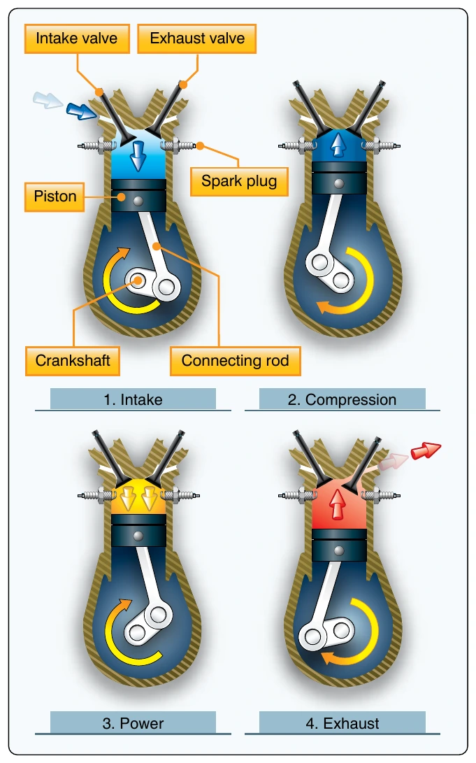
The reciprocating engine consists of a series of pistons connected to a rotating crankshaft. As the pistons move up and down, the crankshaft rotates. The reciprocating engine gets its name from the back-and-forth movement of its internal parts. The four-stroke engine is the most common type, and refers to the four different cycles the engine undergoes to produce power. [Figure 2-56] When the piston moves away from the cylinder head on the intake stroke, the intake valve opens and a mixture of fuel and air is drawn into the combustion chamber. As the cylinder moves back toward the cylinder head, the intake valve closes, and the air-fuel mixture is compressed. When compression is nearly complete, the spark plugs fire and the compressed mixture is ignited to begin the power stroke. The rapidly expanding gases from the controlled burning of the air-fuel mixture drive the piston away from the cylinder head, thus providing power to rotate the crankshaft. The piston then moves back toward the cylinder head on the exhaust stroke where the burned gases are expelled through the opened exhaust valve. Even when the engine is operated at a fairly low speed, the four-stroke cycle takes place several hundred times each minute. In a four-cylinder engine, each cylinder operates on a different stroke. Continuous rotation of a crankshaft is maintained by the precise timing of the power strokes in each cylinder.
Turbine Engine
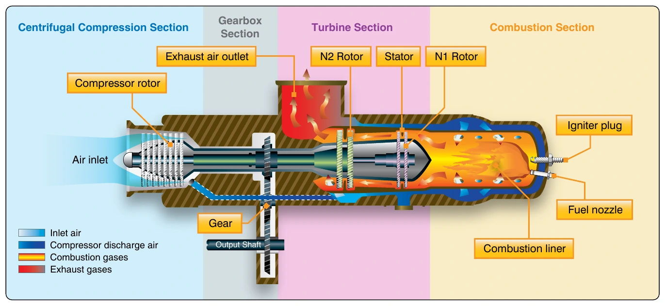
The gas turbine engine mounted on most helicopters is made up of a compressor, combustion chamber, turbine, and accessory gearbox assembly. The compressor draws filtered air into the plenum chamber and compresses it. The compressed air is directed to the combustion section through discharge tubes where atomized fuel is injected into it. The air-fuel mixture is ignited and allowed to expand. This combustion gas is then forced through a series of turbine wheels causing them to turn. These turbine wheels provide power to both the engine compressor and the accessory gearbox. Power is provided to the main rotor and tail rotor systems through the freewheeling unit which is attached to the accessory gearbox power output gear shaft. The combustion gas is finally expelled through an exhaust outlet. [Figure 2-57]
Transmission System
The transmission system transfers power from the engine to the main rotor, tail rotor, and other accessories during normal flight conditions. The main components of the transmission system are the main rotor transmission, tail rotor drive system, clutch, and freewheeling unit. The freewheeling unit, or autorotative clutch, allows the main rotor transmission to drive the tail rotor drive shaft during autorotation. Helicopter transmissions are normally lubricated and cooled with their own oil supply. A sight gauge is provided to check the oil level. Some transmissions have chip detectors located in the sump. These detectors are wired to warning lights located on the pilot’s instrument panel that illuminate in the event of an internal problem. The chip detectors on modern helicopters have a “burn off” capability and attempt to correct the situation without pilot action. If the problem cannot be corrected on its own, the pilot must refer to the emergency procedures for that particular helicopter.
Main Rotor Transmission
The primary purpose of the main rotor transmission is to reduce engine output rpm to optimum rotor rpm. This reduction is different for the various helicopters. As an example, suppose the engine rpm of a specific helicopter is 2,700. A rotor speed of 450 rpm would require a 6:1 reduction. A 9:1 reduction would mean the rotor would turn at 300 rpm. Most helicopters use a dual-needle tachometer or a vertical scale instrument to show both engine and rotor rpm or a percentage of engine and rotor rpm. The rotor rpm indicator normally is used only during clutch engagement to monitor rotor acceleration, and in autorotation to maintain rpm within prescribed limits. [Figure 2-58]
In helicopters with horizontally mounted engines, another purpose of the main rotor transmission is to change the axis of rotation from the horizontal axis of the engine to the vertical axis of the rotor shaft. [Figure 2-59]
Clutch
In a conventional airplane, the engine and propeller are directly connected. However, in a helicopter there is a different relationship between the engine and the rotor. Because of the greater weight of a rotor in relation to the power of the engine, as compared to the weight of a propeller and the power in an airplane, the rotor must be disconnected from the engine when the starter is engaged. A clutch allows the engine to be started and then gradually pick up the load of the rotor.