
Chapter 2
Aerodynamics, Aircraft Assembly, & Rigging
Rotor Blade Tracking
Blade tracking is the process of determining the positions of the tips of the rotor blade relative to each other while the rotor head is turning, and of determining the corrections necessary to hold these positions within certain tolerances. The blades should all track one another as closely as possible. The purpose of blade tracking is to bring the tips of all blades into the same tip path throughout their entire cycle of rotation. Various methods of blade tracking are explained below.
Flag & Pole
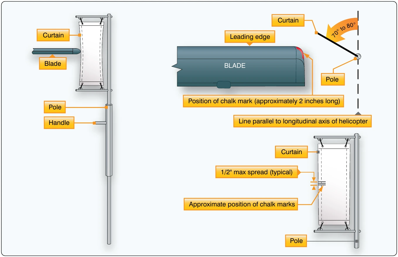
The flag and pole method, as shown in Figure 2-51, shows the relative positions of the rotor blades. The blade tips are marked with chalk or a grease pencil. Each blade tip should be marked with a different color so that it is easy to determine the relationship of the other tips of the rotor blades to each other. This method can be used on all types of helicopters that do not have jet propulsion at the blade tips. Refer to the applicable maintenance manual for specific procedures.
Electronic Blade Tracker
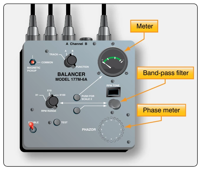
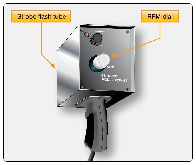
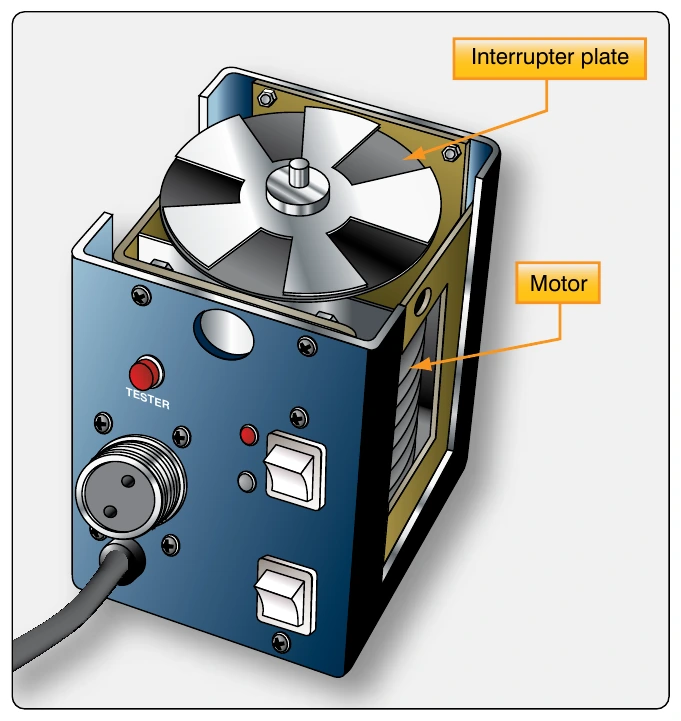
The most common electronic blade tracker consists of a Balancer/Phazor, Strobex tracker, and Vibrex tester. [Figures 2-52 through 2-54] The Strobex blade tracker permits blade tracking from inside or outside the helicopter while on the ground or inside the helicopter in flight. The system uses a highly concentrated light beam flashing in sequence with the rotation of the main rotor blades so that a fixed target at the blade tips appears to be stopped. Each blade is identified by an elongated retroreflective number taped or attached to the underside of the blade in a uniform location. When viewed at an angle from inside the helicopter, the taped numbers will appear normal. Tracking can be accomplished with tracking tip cap reflectors and a strobe light. The tip caps are temporarily attached to the tip of each blade. The high-intensity strobe light flashes in time with the rotating blades. The strobe light operates from the aircraft electrical power supply. By observing the reflected tip cap image, it is possible to view the track of the rotating blades. Tracking is accomplished in a sequence of four separate steps: ground tracking, hover verification, forward flight tracking, and autorotation rpm adjustment.
Tail Rotor Tracking
The marking and electronic methods of tail rotor tracking are explained in the following paragraphs.
Marking Method
Procedures for tail rotor tracking using the marking method, as shown in Figure 2-55, are as follows:
- After replacement or installation of tail rotor hub, blades, or pitch change system, check tail rotor rigging and track tail rotor blades. Tail rotor tip clearance shall be set before tracking and checked again after tracking.
- The strobe-type tracking device may be used if available. Instructions for use are provided with the device. Attach a piece of soft rubber hose six inches long on the end of a ½ × ½ inch pine stick or other flexible device. Cover the rubber hose with Prussian blue or similar type of coloring thinned with oil.
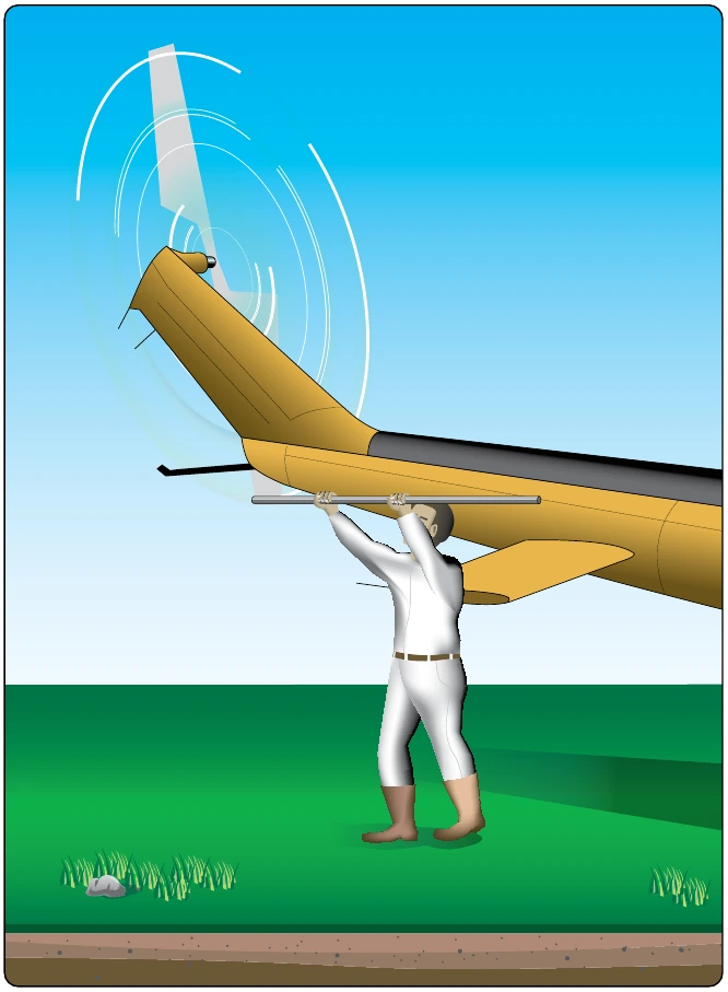
maintenance manual. Run engine with pedals in neutral position. Reset marking device on underside of tail boom assembly. Slowly move marking device into disc of tail rotor approximately one inch from tip. When near blade is marked, stop engine and allow rotor to stop. Repeat this procedure until tracking mark crosses over to the other blade, then extend pitch control link of unmarked blade one half turn.
Electronic Method
The electronic Vibrex balancing and tracking kit is housed in a carrying case and consists of a Model 177M-6A Balancer, a Model 135M-11 Strobex, track and balance charts, an accelerometer, cables, and attaching brackets.