Chapter 2
Aerodynamics, Aircraft Assembly, & Rigging
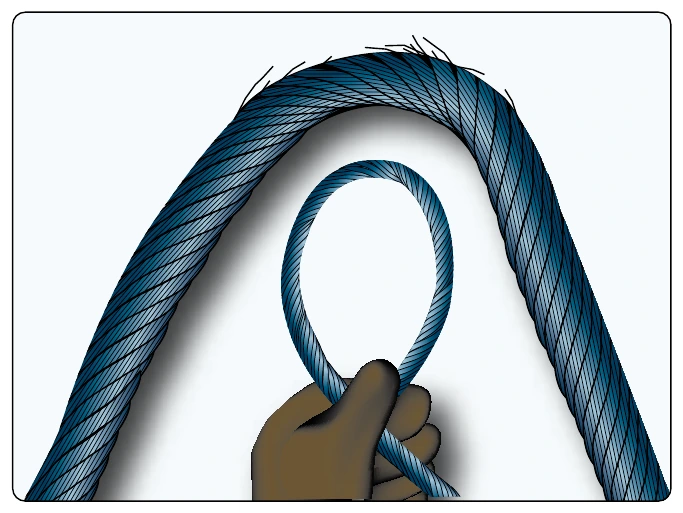
Aircraft cable systems are subject to a variety of environmental conditions and deterioration. Wire or strand breakage is easy to recognize visually. Other kinds of deterioration, such as wear, corrosion, and distortion, are not easily seen. Special attention should be given to areas where cables pass through battery compartments, lavatories, and wheel wells. These are prime areas for corrosion. Special attention should be given to critical fatigue areas. Those areas are defined as anywhere the cable runs over, under, or around a pulley, sleeve, or through a fairlead; or any section where the cable is flexed, rubbed, or within 1 foot of a swaged-on fitting. Close inspection in these critical fatigue areas can be performed by rubbing a rag along the cable. If there are any broken strands, the rag snags on the cable. A more detailed inspection can be performed in areas that may be corroded or indicate a fatigue failure by loosing or removing the cable and bending it. This technique reveals internal broken strands not readily apparent from the outside. [Figure 2-72]
Cable System Installation
Cable Guides
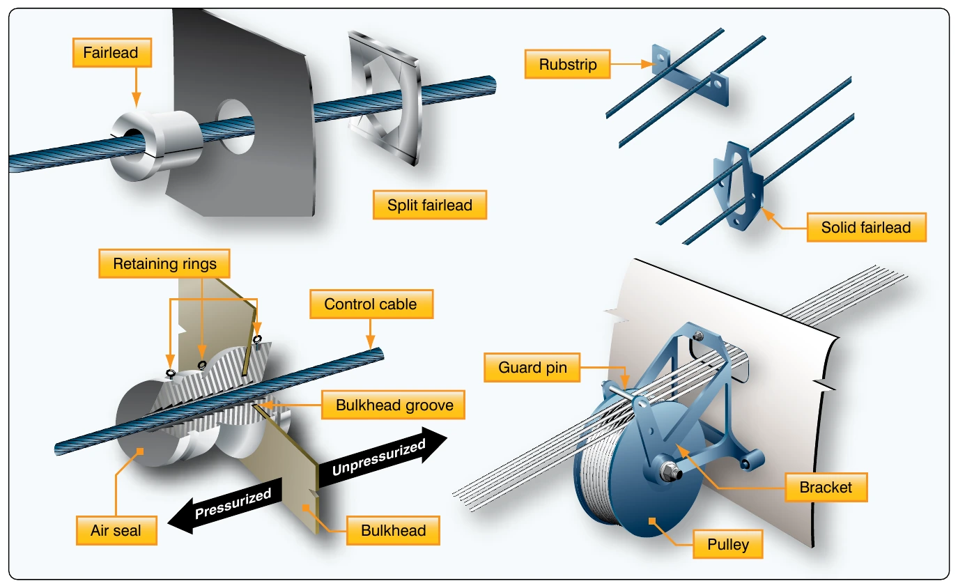
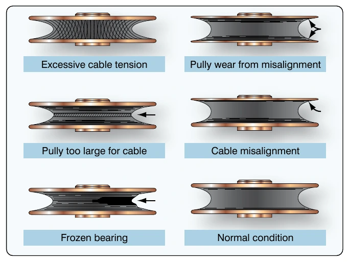
Pulleys are used to guide cables and also to change the direction of cable movement. Pulley bearings are sealed and need no lubrication other than the lubrication done at the factory. Brackets fastened to the structure of the aircraft support the pulleys. Cables passing over pulleys are kept in place by guards. The guards are close fitting to prevent jamming or to prevent the cables from slipping off when they slacken due to temperature variations. Pulleys should be examined to ensure proper lubrication; smooth rotation and freedom from abnormal cable wear patterns which can provide an indication of other problems in the cable system. [Figure 2-73]
Fairleads may be made from a nonmetallic material, such as phenolic, or a metallic material, such as soft aluminum. The fairlead completely encircles the cable where it passes through holes in bulkheads or other metal parts. Fairleads are used to guide cables in a straight line through or between structural members of the aircraft. Fairleads should never deflect the alignment of a cable more than 3° from a straight line.
Pressure seals are installed where cables (or rods) move through pressure bulkheads. The seal grips tightly enough to prevent excess air pressure loss but not enough to hinder movement of the cable. Pressure seals should be inspected at regular intervals to determine that the retaining rings are in place. If a retaining ring comes off, it may slide along the cable and cause jamming of a pulley. [Figure 2-74]
Travel Adjustment
Control surfaces should move a certain distance in either direction from the neutral position. These movements must be synchronized with the movement of the flight deck controls. The flight control system must be adjusted (rigged) to obtain these requirements. The tools for measuring surface travel primarily include protractors, rigging fixtures, contour templates, and rulers. These tools are used when rigging flight control systems to assure that the desired travel has been obtained. Generally speaking, the rigging consists of the following:
- Positioning the flight control system in neutral and temporarily locking it there with rig pins or blocks;
- Adjusting system cable tension and maintaining rudder, elevator, and ailerons in the neutral position; and
- Adjusting the control stops to the aircraft manufacturer’s specifications.
Cable Tension
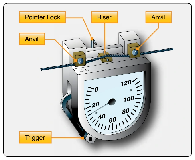
For the aircraft to operate as it was designed, the cable tension for the flight controls must be correct. To determine the amount of tension on a cable, a tensiometer is used. When properly maintained, a tensiometer is 98 percent accurate. Cable tension is determined by measuring the amount of force needed to make an offset in the cable between two hardened steel blocks called anvils. A riser or plunger is pressed against the cable to form the offset. Several manufacturers make a variety of tensiometers, each type designed for different kinds of cable, cable sizes, and cable tensions. [Figure 2-75]
Rigging Fixtures
Rigging fixtures and templates are special tools (gauges) designed by the manufacturer to measure control surface travel. Markings on the fixture or template indicate desired control surface travel.