
Chapter 2
Aerodynamics, Aircraft Assembly, & Rigging
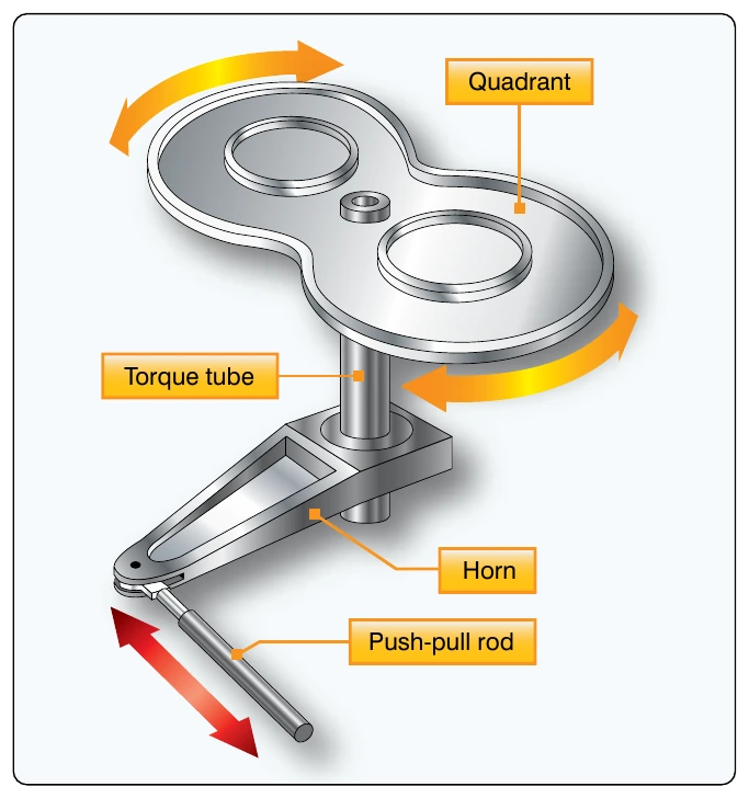
Where an angular or twisting motion is needed in a control system, a torque tube is installed. Figure 2-81 shows how a torque tube is used to transmit motion in opposite directions.
Cable Drums
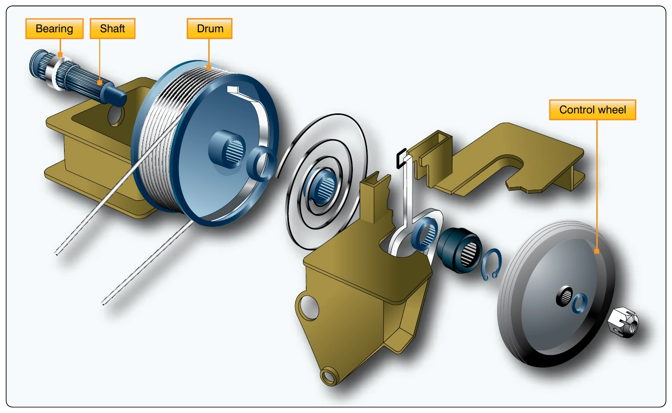
Cable drums are used primarily in trim tab systems. As the trim tab control wheel is moved clockwise or counterclockwise, the cable drum winds or unwinds to actuate the trim tab cables. [Figure 2-82]
Rigging Checks
All aircraft assembly and rigging must be performed in accordance with the requirements prescribed by the specific aircraft and/or aircraft component manufacturer. Correctly following the procedures provides for proper operation of the components in regard to their mechanical and aerodynamic function and ensures the structural integrity of the aircraft. Rigging procedures are detailed in the applicable manufacturer’s maintenance or service manuals and applicable structural repair manuals. Additionally, aircraft specification or TCDS also provide information regarding control surface movement and weight and balance limits.
The purpose of this section is to explain the methods of checking the relative alignment and adjustment of an aircraft’s main structural components. It is not intended to imply that the procedures are exactly as they may be in a particular aircraft. When rigging an aircraft, always follow the procedures and methods specified by the aircraft manufacturer.
Structural Alignment
The position or angle of the main structural components is related to a longitudinal datum line parallel to the aircraft center line and a lateral datum line parallel to a line joining the wing tips. Before checking the position or angle of the main components, the aircraft must be jacked and leveled.
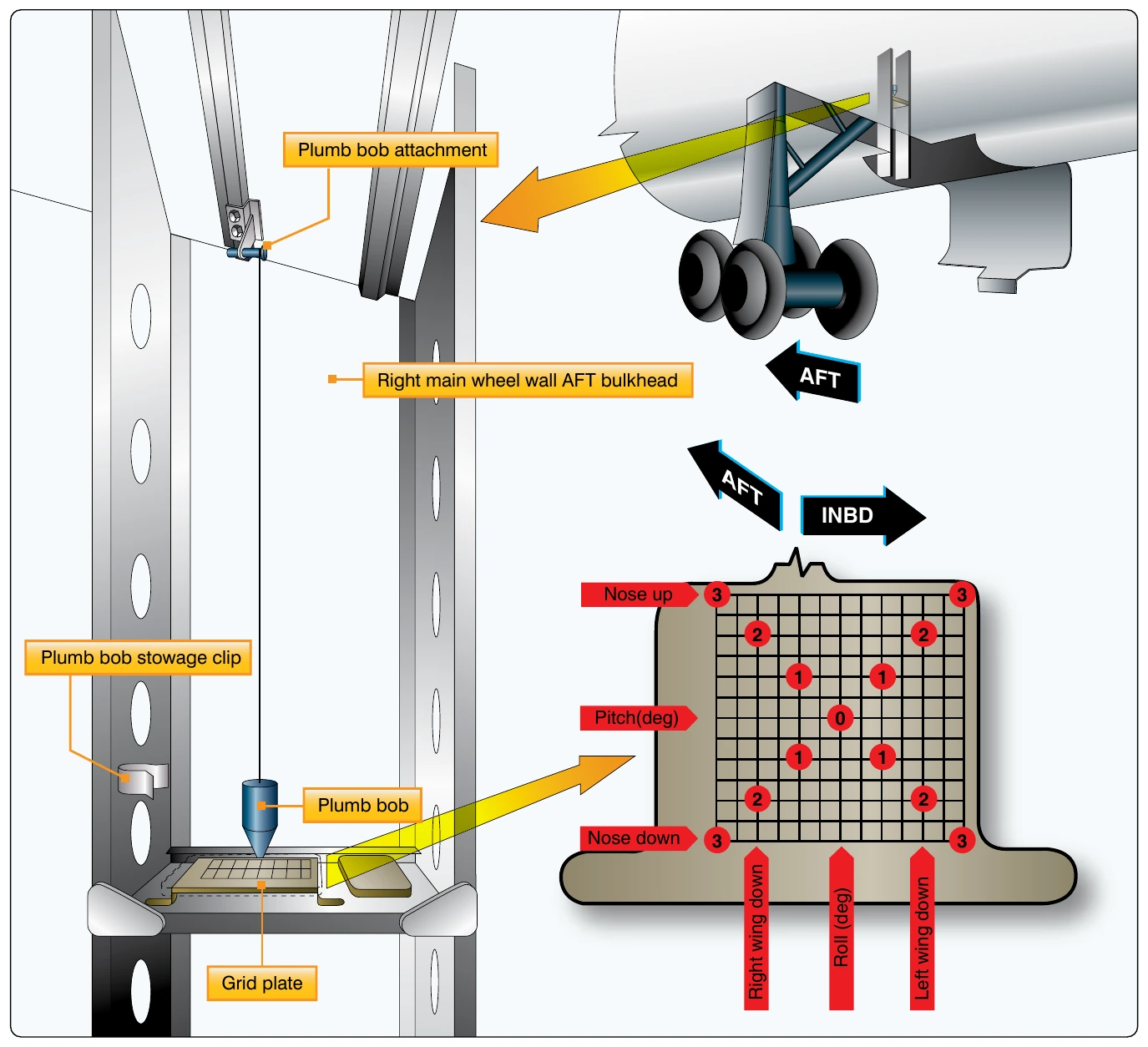
Small aircraft usually have fixed pegs or blocks attached to the fuselage parallel to or coincident with the datum lines. A spirit level and a straight edge are rested across the pegs or blocks to check the level of the aircraft. This method of checking aircraft level also applies to many of the larger types of aircraft. However, the grid method is sometimes used on large aircraft. The grid plate is a permanent fixture installed on the aircraft floor or supporting structure. [Figure 2-83]
When the aircraft is to be leveled, a plumb bob is suspended from a predetermined position in the ceiling of the aircraft over the grid plate. The adjustments to the jacks necessary to level the aircraft are indicated on the grid scale. The aircraft is level when the plumb bob is suspended over the center point of the grid.
Certain precautions must be observed in all instances when jacking an aircraft. Normally, rigging and alignment checks should be performed in an enclosed hangar. If this cannot be accomplished, the aircraft should be positioned with the nose into the wind.
The weight and loading of the aircraft should be exactly as described in the manufacturer’s manual. In all cases, the aircraft should not be jacked until it is determined that the maximum jacking weight (if applicable) specified by the manufacturer is not exceeded.
With a few exceptions, the dihedral and incidence angles of conventional modern aircraft cannot be adjusted. Some manufacturers permit adjusting the wing angle of incidence to correct for a wing-heavy condition. The dihedral and incidence angles should be checked after hard landings or after experiencing abnormal flight loads to ensure that the components are not distorted and that the angles are within the specified limits.
There are several methods for checking structural alignment and rigging angles. Special rigging boards that incorporate, or on which can be placed, a special instrument (spirit level or inclinometer) for determining the angle are used on some aircraft. On a number of aircraft, the alignment is checked using a transit and plumb bobs or a theodolite and sighting rods. The particular equipment to use is usually specified in the manufacturer’s maintenance manual.
When checking alignment, a suitable sequence should be developed and followed to be certain that the checks are made at all the positions specified. The alignment checks specified usually include:
- Wing dihedral angle
- Wing incidence angle
- Verticality of the fin
- Engine alignment
- A symmetry check
- Horizontal stabilizer incidence
- Horizontal stabilizer dihedral