Chapter 2
Aerodynamics, Aircraft Assembly, & Rigging
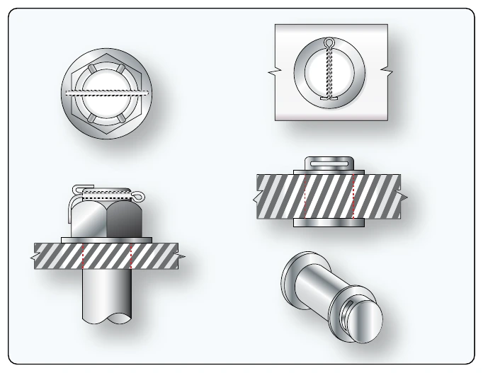
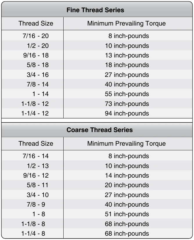
Pal nuts may be a second nut tightened against the first and used to force the primary nut thread against the bolt or screw thread. They may also be of the type that are made of stamped spring steel and are to be used only once and replaced with new ones when removed.
Biplane Assembly & Rigging
Biplanes were some of the very first aircraft designs. The first powered heavier-than-air aircraft, the Wright Brothers’ Wright Flyer, successfully flown on December 17, 1903, was a biplane.
The first biplanes were designed with very thin wing sections and, consequently, the wing structure needed to be strengthened by external bracing wires. The biplane configuration allowed the two wings to be braced against one another, increasing the structural strength. When the assembly and rigging of a biplane is accomplished in accordance with the approved instructions, a stable airworthy aircraft is the
result.
Whether assembling an early model vintage aircraft that may have been disassembled for repair and restoration, or constructing and assembling a new aircraft, the following are some basic alignment procedures to follow.
To start, the fuselage must be level, fore and aft and laterally. The aircraft usually has specific leveling points designated by the manufacturer or indicated on the plans. The fuselage should be blocked up off the landing gear so it is stable. A center line should be drawn on the floor the length of the fuselage and another line perpendicular to it at the firewall, for use as an additional alignment reference.
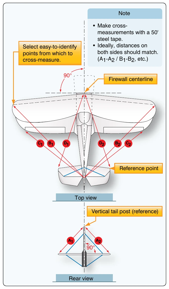
With the horizontal and vertical tail surfaces installed, the incident angle for the horizontal stabilizer should be set. The tail brace wires should be connected and tightened until the slack is removed. Alignment measurements should be checked as shown in Figure 2-96.
Install the elevator and rudder and clamp them in a neutral position. Verify the neutral position of the control stick and rudder pedals in the flight deck and secure them in order to simplify the connecting and final tensioning of the control cables.
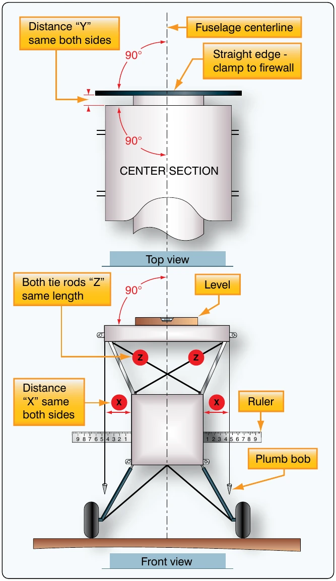
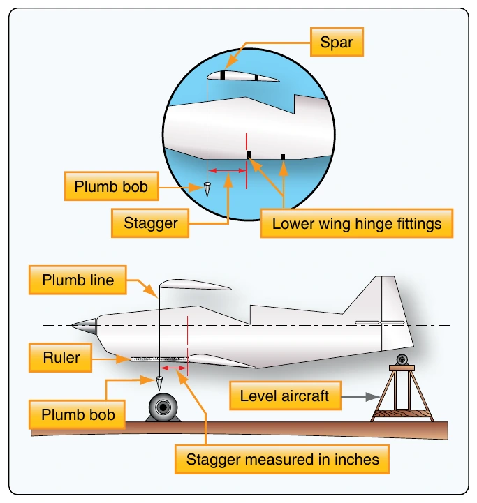
If the biplane has a center section for the upper wing, it must be aligned as accurately as possible, because even the smallest error is compounded at the wing tip. Applicable cables and turnbuckles should be connected and the tension set as specified. [Figure 2-97] The stagger measurement can be checked as shown in Figure 2-98.
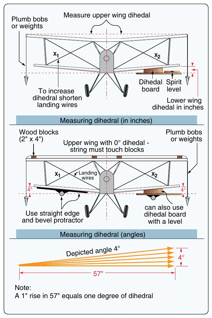
The lower wing sections should be individually attached to the fuselage and blocked up for support while the landing wires are connected and adjusted to obtain the dihedral called for in the specifications or plans. [Figure 2-99]
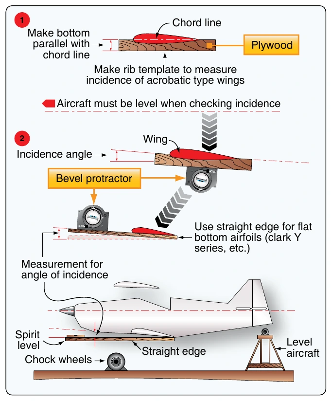
Next, connect the outer “N” struts to the left and right sections of the lower wing. Now, the upper wing can be attached and the flying wires installed. The slave struts can be installed and the ailerons connected using the same alignment and adjustment procedures used for the elevator and rudder. The incidence angle can be checked, as shown in Figure 2-100.