
Chapter 2
Aerodynamics, Aircraft Assembly, & Rigging
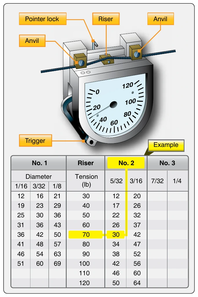
Following the manufacturer’s instructions, lower the trigger. Then, place the cable to be tested under the two anvils and close the trigger (move it up). Movement of the trigger pushes up the riser, which pushes the cable at right angles to the two clamping points under the anvils. The force that is required to do this is indicated by the dial pointer. As the sample chart beneath the illustration shows, different numbered risers are used with different size cables. Each riser has an identifying number and is easily inserted into the tensiometer.
Included with each tensiometer is a conversion chart, which is used to convert the dial reading to pounds. The dial reading is converted to pounds of tension as follows. Using a No. 2 riser to measure the tension of a 5/32" diameter cable, a reading of 30 is obtained. The actual tension (see chart) of the cable is 70 lbs. Referring to the chart, also notice that a No. 1 riser is used with 1/16", 3/32", and 1/8" cable. Since the tensiometer is not designed for use in measuring 7/32" or 1/4" cable, no values are shown in the No. 3 riser column of the chart.
When actually taking a reading of cable tension in an aircraft, it may be difficult to see the dial. Therefore, a pointer lock is built in on the tensiometer. Push it in to lock the pointer, then remove the tensiometer from the cable and observe the reading. After observing the reading, pull the lock out and the pointer returns to zero.
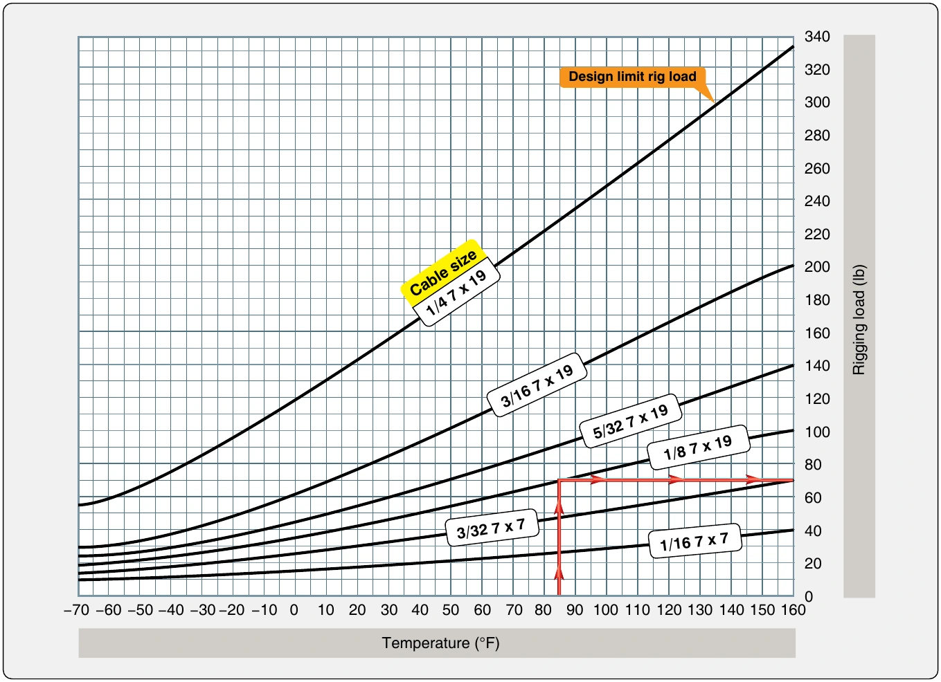
Another variable that must be taken into account when adjusting cable tension is the ambient temperature of cable and the aircraft. To compensate for temperature variations, cable rigging charts are used when establishing cable tensions in flight control, landing gear, and other cable-operated systems. [Figure 2-89]
To use the chart, determine the size of the cable that is to be adjusted and the ambient air temperature. For example, assume that the cable size is 1/8" diameter, which is a 7-19 cable and the ambient air temperature is 85 °F. Follow the 85 °F line upward to where it intersects the curve for 1/8" cable. Extend a horizontal line from the point of intersection to the right edge of the chart. The value at this point indicates the tension (rigging load in pounds) to establish on the cable. The tension for this example is 70 pounds.
Control Surface Travel
In order for a control system to function properly, it must be correctly adjusted. Correctly rigged control surfaces move through a prescribed arc (surface-throw) and are synchronized with the movement of the flight deck controls. Rigging any control system requires that the aircraft manufacturer’s instructions be followed as outlined in their maintenance manual.
Therefore, the explanations in this chapter are limited to the three general steps listed below:
- Lock the flight deck control, bellcranks, and the control surfaces in the neutral position.
- Adjust the cable tension, maintaining the rudder, elevators, or ailerons in the neutral position.
- Adjust the control stops to limit the control surface travel to the dimensions given for the aircraft being rigged.
The range of movement of the controls and control surfaces should be checked in both directions from neutral. There are various tools used for measuring surface travel, including protractors, rigging fixtures, contour templates, and rulers. These tools are used when rigging flight control systems to ensure that the aircraft is properly rigged and the manufacturer’s specifications have been complied with.
Rigging fixtures and contour templates are special tools (gauges) designed by the manufacturer to measure control surface travel. Markings on the fixture or template indicate desired control surface travel. In many instances, the aircraft manufacturer gives the travel of a particular control surface in degrees and inches. If the travel in inches is provided, a ruler can be used to measure surface travel in inches.
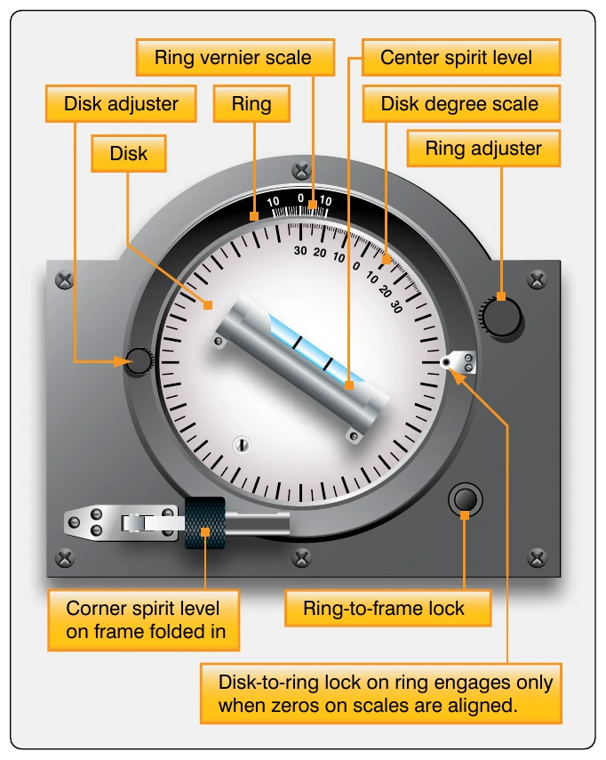
Protractors are tools for measuring angles in degrees. Various types of protractors are used to determine the travel of flight control surfaces. One protractor that can be used to measure aileron, elevator, or wing flap travel is the universal propeller protractor shown in Figure 2-90.
This protractor is made up of a frame, disc, ring, and two spirit levels. The disc and ring turn independently of each other and of the frame. (The center spirit level is used to position the frame vertically when measuring propeller blade angle.) The center spirit level is used to position the disc when measuring control surface travel. A disc-to-ring lock is provided to secure the disc and ring together when the zero on the ring vernier scale and the zero on the disc degree scale align. The ring-to-frame lock prevents the ring from moving when the disc is moved. Note that they start at the same point and advance in opposite directions. A double 10-part vernier is marked on the ring.
The rigging of the trim tab systems is performed in a similar manner. The trim tab control is set to the neutral (no trim) position, and the surface tab is usually adjusted to streamline with the control surface. However, on some aircraft, the specifications may require that the trim tabs be offset a degree or two from streamline when in the neutral position. After the tab and tab control are in the neutral position, adjust the control cable tension.
Pins, usually called rig pins, are sometimes used to simplify the setting of pulleys, levers, bellcranks, etc., in their neutral positions. A rig pin is a small metallic pin or clip. When rig pins are not provided, the neutral positions can be established by means of alignment marks, by special templates, or by taking linear measurements.
If the final alignment and adjustment of a system are correct, it should be possible to withdraw the rigging pins easily. Any undue tightness of the pins in the rigging holes indicates incorrect tensioning or misalignment of the system.