
Chapter 2
Aerodynamics, Aircraft Assembly, & Rigging
After a system has been adjusted, the full and synchronized movement of the controls should be checked. When checking the range of movement of the control surface, the controls must be operated from the flight deck and not by moving the control surfaces. During the checking of control surface travel, ensure that chains, cables, etc., have not reached the limit of their travel when the controls are against their respective stops.
Adjustable and nonadjustable stops (whichever the case requires) are used to limit the throw-range or travel movement of the ailerons, elevator, and rudder. Usually there are two sets of stops for each of the three main control surfaces. One set is located at the control surface, either in the snubber cylinders or as structural stops; the other, at the flight deck control. Either of these may serve as the actual limit stop. However, those situated at the control surface usually perform this function. The other stops do not normally contact each other, but are adjusted to a definite clearance when the control surface is at the full extent of its travel. These work as override stops to prevent stretching of cables and damage to the control system during violent maneuvers. When rigging control systems, refer to the applicable maintenance manual for the sequence of steps for adjusting these stops to limit the control surface travel.
Where dual controls are installed, they must be synchronized and function satisfactorily when operated from both positions.
Trim tabs and other tabs should be checked in a manner similar to the main control surfaces. The tab position indicator must be checked to see that it functions correctly. If jackscrews are used to actuate the trim tab, check to see that they are not extended beyond the specified limits when the tab is in its extreme positions.
After determining that the control system functions properly and is correctly rigged, it should be thoroughly inspected to determine that the system is correctly assembled and operates freely over the specified range of movement.
Checking & Safetying the System
Whenever rigging is performed on any aircraft, it is good practice to have a second set of eyes inspect the control system to make certain that all turnbuckles, rod ends, and attaching nuts and bolts are correctly safetied.
As a general rule, all fasteners on an aircraft are safetied in some manner. Safetying is defined as securing by various means any nut, bolt, turnbuckle, etc., on the aircraft so that vibration does not cause it to loosen during operation.
Most aircraft manufacturers have a Standard Practices section in their maintenance manuals. These are the methods that should be used when working on a particular system of a specific aircraft. However, most standard aircraft hardware has a standard method of being safetied. The following information provides some of the most common methods used in aircraft safetying.
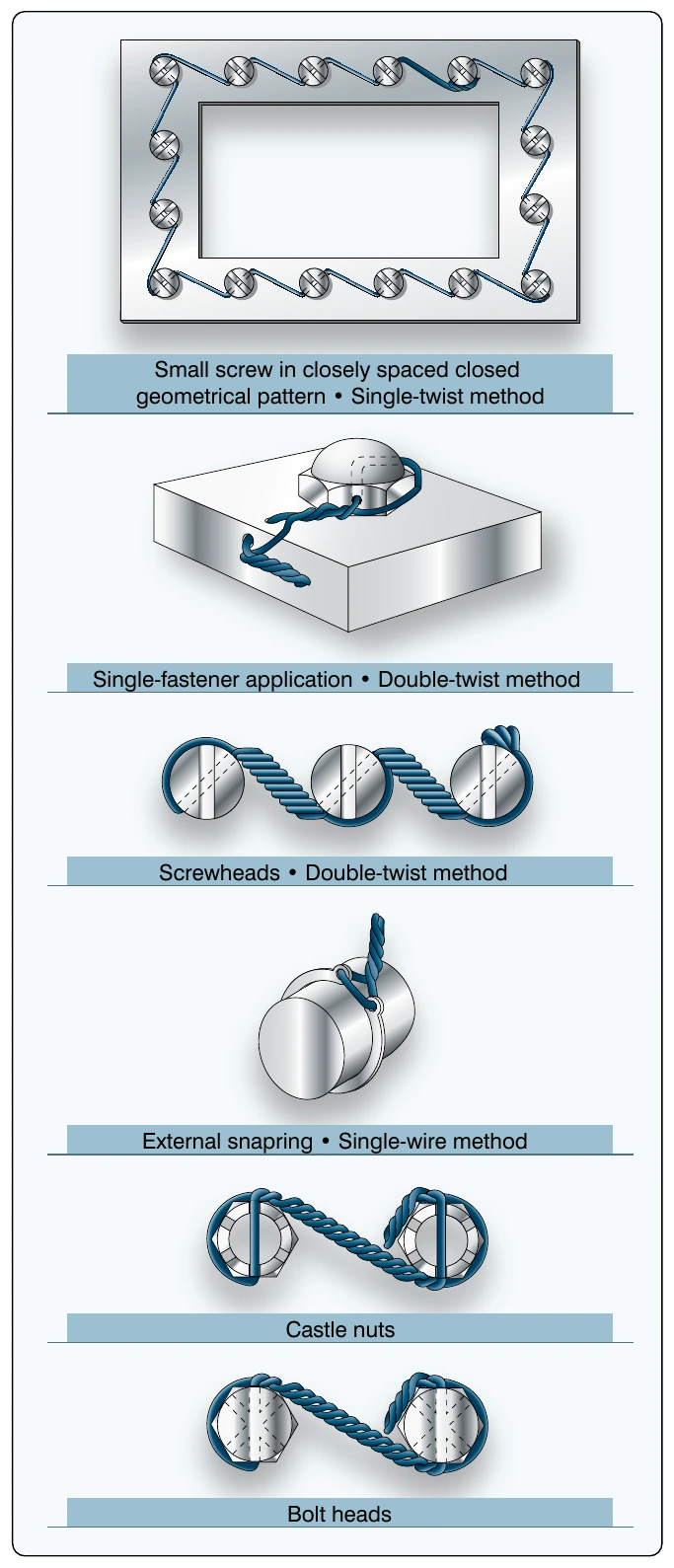
The most commonly used safety wire method is the double-twist, utilizing stainless steel or Monel wire in the.032 to.040-inch diameter range. This method is used on studs, cable turnbuckles, flight controls, and engine accessory attaching bolts. A single-wire method is used on smaller screws, bolts, and/or nuts when they are located in a closely spaced or closed geometrical pattern. The single-wire method is also used on electrical components and in places that are difficult to reach. [Figure 2-91]
Safety-of-flight emergency equipment, such as portable fire extinguishers, oxygen regulators, emergency valves, firewall shut-offs, and seals on first-aid kits, are safetied using a single copper wire (.020-inch diameter) or aluminum wire (.031-inch diameter). The wire on this emergency equipment is installed only to indicate the component is sealed or has not been actuated. It must be possible to break the wire seal by hand, without the use of any tools.
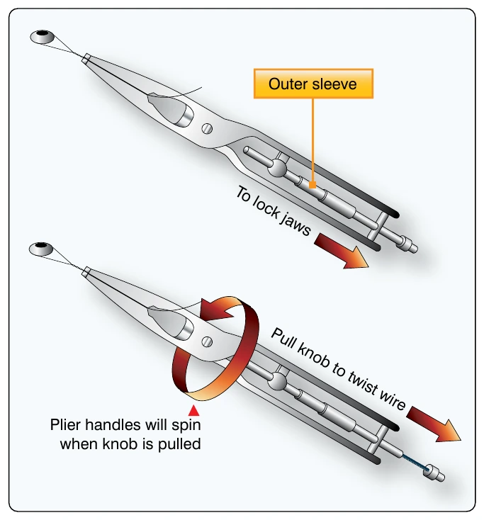
The use of safety wire pliers, or wire twisters, makes the job of safetying much easier on the mechanic’s hands and produces a better finished product. [Figure 2-92]
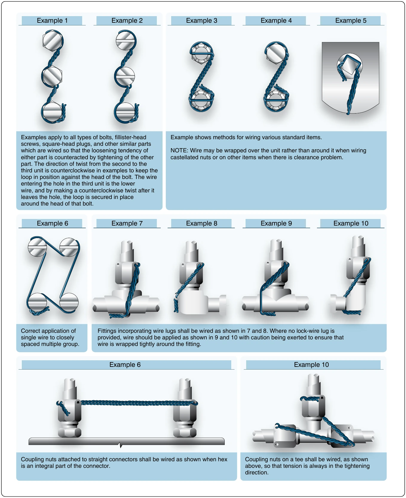
The wire should have six to eight twists per inch of wire and be pulled taut while being installed. Where practicable, install the safety wire around the head of the fastener and twist it in such a manner that the loop of the wire is pulled close to the contour of the unit being safety wired, and in the direction that would have the tendency to tighten the fastener. [Figure 2-93] Cotter pins are used to secure such items as bolts, screws, pins, and shafts. They are used at any location where a turning or actuating movement takes place. The diameter of the cotter pin selected for any application should be the largest size that will fit consistent with the diameter of the cotter pin hole and/or the slots in the castellated nut. Cotter pins, like safety wire, should never be re-used on aircraft. [Figure 2-94]
Self-locking nuts are used in applications where they are not removed often. There are two types of self-locking nuts currently in use. One is all metal and the other has an insert, usually of fiber or nylon.
It is extremely important that the manufacturer’s Illustrated Parts Book (IPB) be consulted for the correct type and grade of lock nut for various locations on the aircraft. The finish or plating color of the nut identifies the type of application and environment in which it can be used. For example, a cadmium-plated nut is gold in color and provides exceptionally good protection against corrosion, but should not be used in applications where the temperature may exceed 450 °F.
Repeated removal and installation causes the self-locking nut to lose its locking feature. They should be replaced when they are no longer capable of maintaining the minimum prevailing torque. [Figure 2-95]
Lock washers may be used with bolts and machine screws whenever a self-locking nut or castellated nut is not applicable. They may be of the split washer spring type, or a multi-serrated internal or external star washer.