
Chapter 4
Aircraft Metal Structural Repair
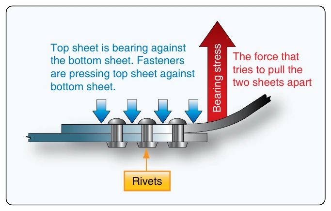
Bearing stress resists the force that the rivet or bolt places on the hole. As a rule, the strength of the fastener should be such that its total shear strength is approximately equal to the total bearing strength of the sheet material. [Figure 4-2]
Torsion
Torsion is the stress that produces twisting. While moving the aircraft forward, the engine also tends to twist it to one side, but other aircraft components hold it on course. Thus, torsion is created. The torsional strength of a material is its resistance to twisting or torque (twisting stress). The stresses arising from this action are shear stresses caused by the rotation of adjacent planes past each other around a common reference axis at right angles to these planes. This action may be illustrated by a rod fixed solidly at one end and twisted by a weight placed on a lever arm at the other, producing the equivalent of two equal and opposite forces acting on the rod at some distance from each other. A shearing action is set up all along the rod, with the center line of the rod representing the neutral axis.
Bending
Bending (or beam stress) is a combination of compression and tension. The rod in Figure 4-1E has been shortened (compressed) on the inside of the bend and stretched on the outside of the bend. Note that the bending stress causes a tensile stress to act on the upper half of the beam and a compressive stress on the lower half. These stresses act in opposition on the two sides of the center line of the member, which is called the neutral axis. Since these forces acting in opposite directions are next to each other at the neutral axis, the greatest shear stress occurs along this line, and none exists at the extreme upper or lower surfaces of the beam.
Tools for Sheet Metal Construction & Repair
Without modern metalworking tools and machines, the job of the airframe technician would be more difficult and tiresome, and the time required to finish a task would be much greater. These specialized tools and machines help the airframe technician construct or repair sheet metal in a faster, simpler, and better manner than possible in the past. Powered by human muscle, electricity, or compressed air, these tools are used to lay out, mark, cut, sand, or drill sheet metal.
Layout Tools
Before fitting repair parts into an aircraft structure, the new sections must be measured and marked, or laid out to the dimensions needed to make the repair part. Tools utilized for this process are discussed in this section.
Scales
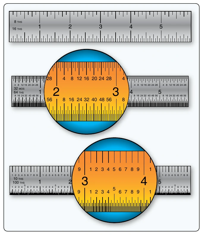
Scales are available in various lengths, with the 6-inch and 12-inch scales being the most common and affordable. A scale with fractions on one side and decimals on the other side is very useful. To obtain an accurate measurement, measure with the scale held on edge from the 1-inch mark instead of the end. Use the graduation marks on the side to set a divider or compass. [Figure 4-3]
Combination Square
A combination square consists of a steel scale with three heads that can be moved to any position on the scale and locked in place. The three heads are a stock head that measures 90° and 45° angles, a protractor head that can measure any angle between the head and the blade, and a center head that uses one side of the blade as the bisector of a 90° angle. The center of a shaft can be found by using the center head. Place the end of the shaft in the V of the head and scribe a line along the edge of the scale. Rotate the head about 90° and scribe another line along the edge of the scale. The two lines will cross at the center of the shaft. [Figure 4-4]
Dividers
Dividers are used to transfer a measurement from a device to a scale to determine its value. Place the sharp points at the locations from which the measurement is to be taken. Then, place the points on a steel machinist’s scale, but put one of the points on the 1-inch mark and measure from there. [Figure 4-5]
Rivet Spacers
A rivet spacer is used to make a quick and accurate rivet pattern layout on a sheet. On the rivet spacer, there are alignment marks for 1⁄2-inch, 3⁄4-inch, 1-inch and 2-inch rivet spacing. [Figure 4-6]