
Chapter 4
Aircraft Metal Structural Repair
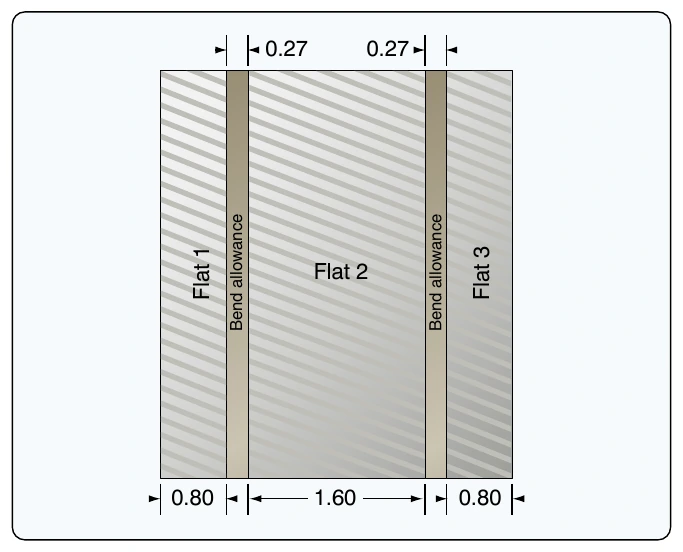
Step 6: Flat Pattern Lay Out
After a flat pattern layout of all relevant information is made, the material can be cut to the correct size, and the bend tangent lines can be drawn on the material. [Figure 4-130]
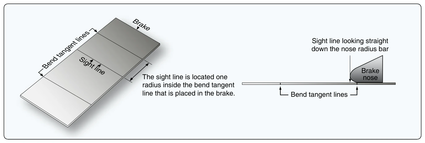
Step 7: Draw the Sight Lines on the Flat Pattern
The pattern laid out in Figure 4-130 is complete, except for a sight line that needs to be drawn to help position the bend tangent line directly at the point where the bend should start. Draw a line inside the bend allowance area that is one bend radius away from the bend tangent line that is placed under the brake nose bar. Put the metal in the brake under the clamp and adjust the position of the metal until the sight line is directly below the edge of the radius bar. [Figure 4-131] Now, clamp the brake on the metal and raise the leaf to make the bend. The bend begins exactly on the bend tangent line.
Using a J-Chart to Calculate Total Developed Width
The J-chart, often found in the SRM, can be used to determine bend deduction or setback and the TDW of a flat pattern layout when the inside bend radius, bend angle, and material thickness are known. [Figure 4-132] While not as accurate as the traditional layout method, the J-chart provides sufficient information for most applications. The J-chart does not require difficult calculations or memorized formulas because the required information can be found in the repair drawing or can be measured with simple measuring tools.
When using the J-chart, it is helpful to know whether the angle is open (greater than 90°) or closed (less than 90°) because the lower half of the J-chart is for open angles and the upper half is for closed angles.
To find the total developed width using a J-chart:
- Place a straightedge across the chart and connect the bend radius on the top scale with the material thickness on the bottom scale. [Figure 4-132]
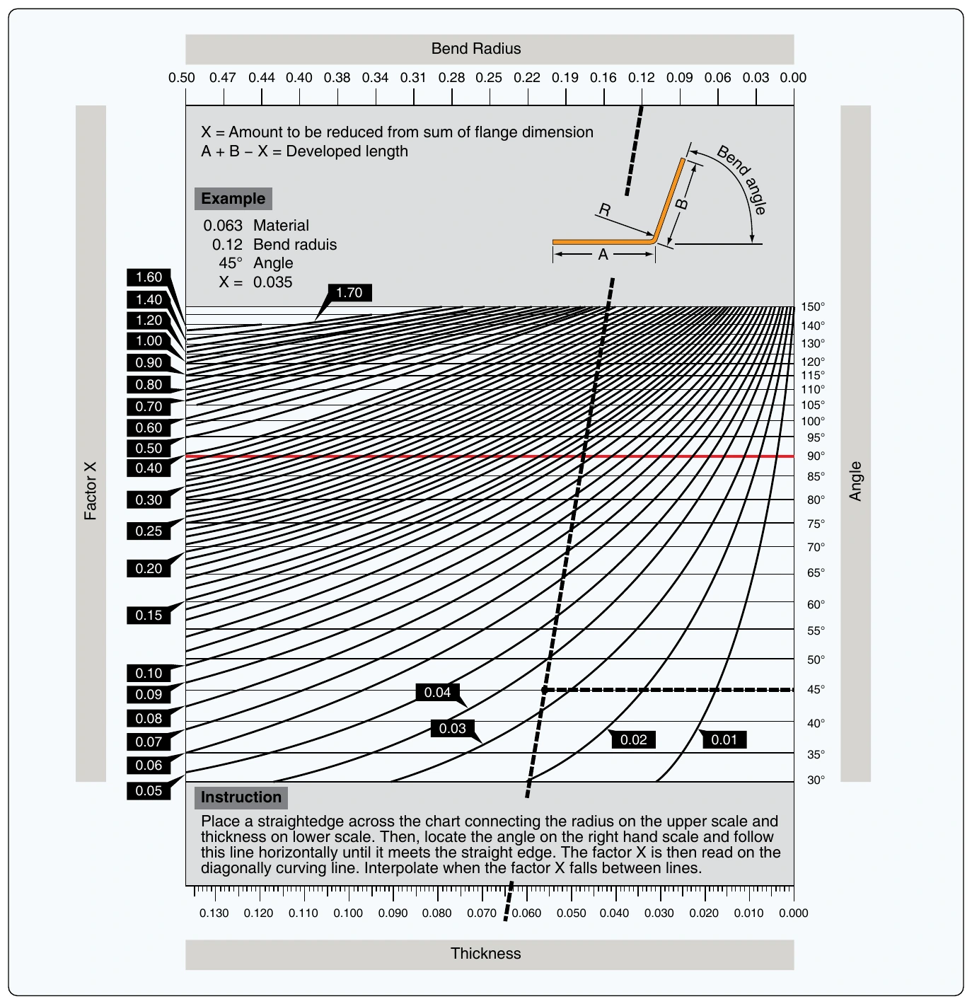
- Locate the angle on the right hand scale and follow this line horizontally until it meets the straight edge.
- The factor X (bend deduction) is then read on the diagonally curving line.
- Interpolate when the X factor falls between lines.
- Add up the mold line dimensions and subtract the X factor to find the TDW.
Example 1
Use a straightedge to connect the bend radius (0.22-inch) at the top of the graph with the material thickness at the bottom (0.063-inch). Locate the 90° angle on the right hand scale and follow this line horizontally until it meets the straightedge. Follow the curved line to the left and find 0.17 at the left side. The X factor in the drawing is 0.17-inch. [Figure 4-133]