
Chapter 4
Aircraft Metal Structural Repair
The flats, or flat portions of the U-channel, are equal to the mold line dimension minus the setback for each of the sides, and the mold line length minus two setbacks for the center flat. Two setbacks need to be subtracted from the center flat because this flat has a bend on either side.
The flat dimension for the sample U-channel is calculated in
Step 4: Find the Bend Allowance
When making a bend or fold in a piece of metal, the bend allowance or length of material required for the bend must be calculated. Bend allowance depends on four factors: degree of bend, radius of the bend, thickness of the metal, and type of metal used.
The radius of the bend is generally proportional to the thickness of the material. Furthermore, the sharper the radius of bend, the less the material that is needed for the bend. The type of material is also important. If the material is soft, it can be bent very sharply; but if it is hard, the radius of bend is greater, and the bend allowance is greater. The degree of bend affects the overall length of the metal, whereas the thickness influences the radius of bend.
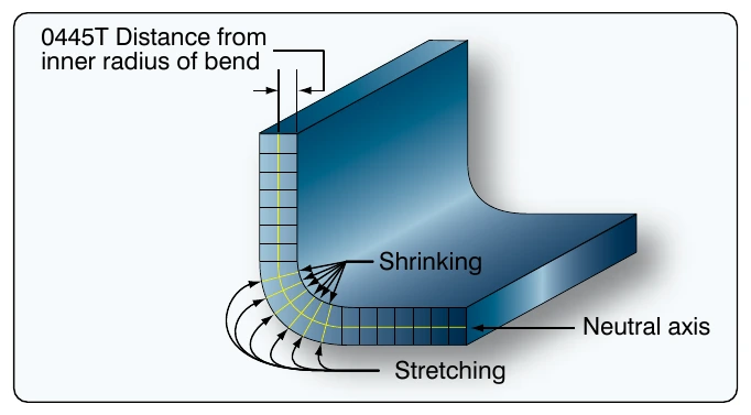
Bending a piece of metal compresses the material on the inside of the curve and stretches the material on the outside of the curve. However, at some distance between these two extremes lies a space which is not affected by either force. This is known as the neutral line or neutral axis and occurs at a distance approximately 0.445 times the metal thickness (0.445 × T) from the inside of the radius of the bend. [Figure 4-126]
The length of this neutral axis must be determined so that sufficient material can be provided for the bend. This is called the bend allowance. This amount must be added to the overall length of the layout pattern to ensure adequate material for the bend. To save time in calculation of the bend allowance, formulas and charts for various angles, radii of bends, material thicknesses, and other factors have been developed.
Formula 1: Bend Allowance for a 90° Bend To the radius of bend (R) add 1⁄2 the thickness of the metal (1⁄2T). This gives R + 1⁄2T, or the radius of the circle of the neutral axis. [Figure 4-127] Compute the circumference of this circle by multiplying the radius of the neutral line
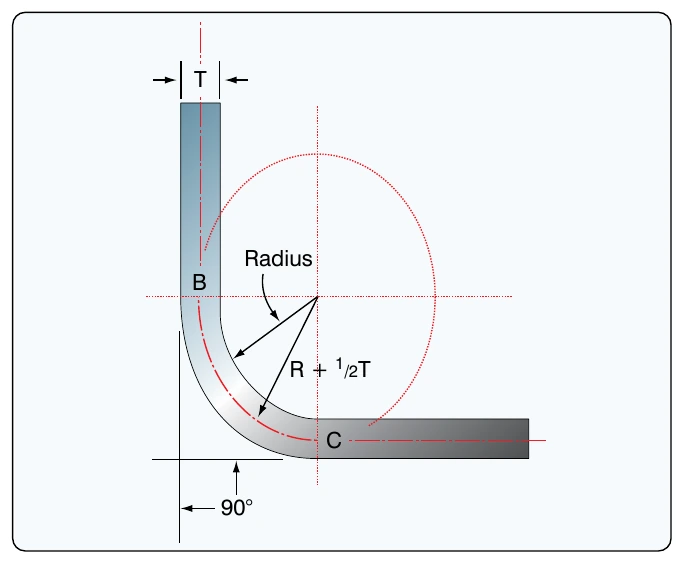
This is the bend allowance for a 90° bend. To use the formula for a 90° bend having a radius of 1⁄4 inch for material 0.051-inch thick, substitute in the formula as follows.
The bend allowance, or the length of material required for the bend, is 0.4327 or 7⁄16-inch.
Formula 2: Bend Allowance for a 90° Bend This formula uses two constant values that have evolved over a period of years as being the relationship of the degrees in the bend to the thickness of the metal when determining the bend allowance for a particular application. By experimentation with actual bends in metals, aircraft engineers have found that accurate bending results could be obtained by using the following formula for any degree of bend from 1° to 180°.
To use this formula for a 90° bend having a radius of.16-inch for material 0.040-inch thick, substitute in the formula as follows: