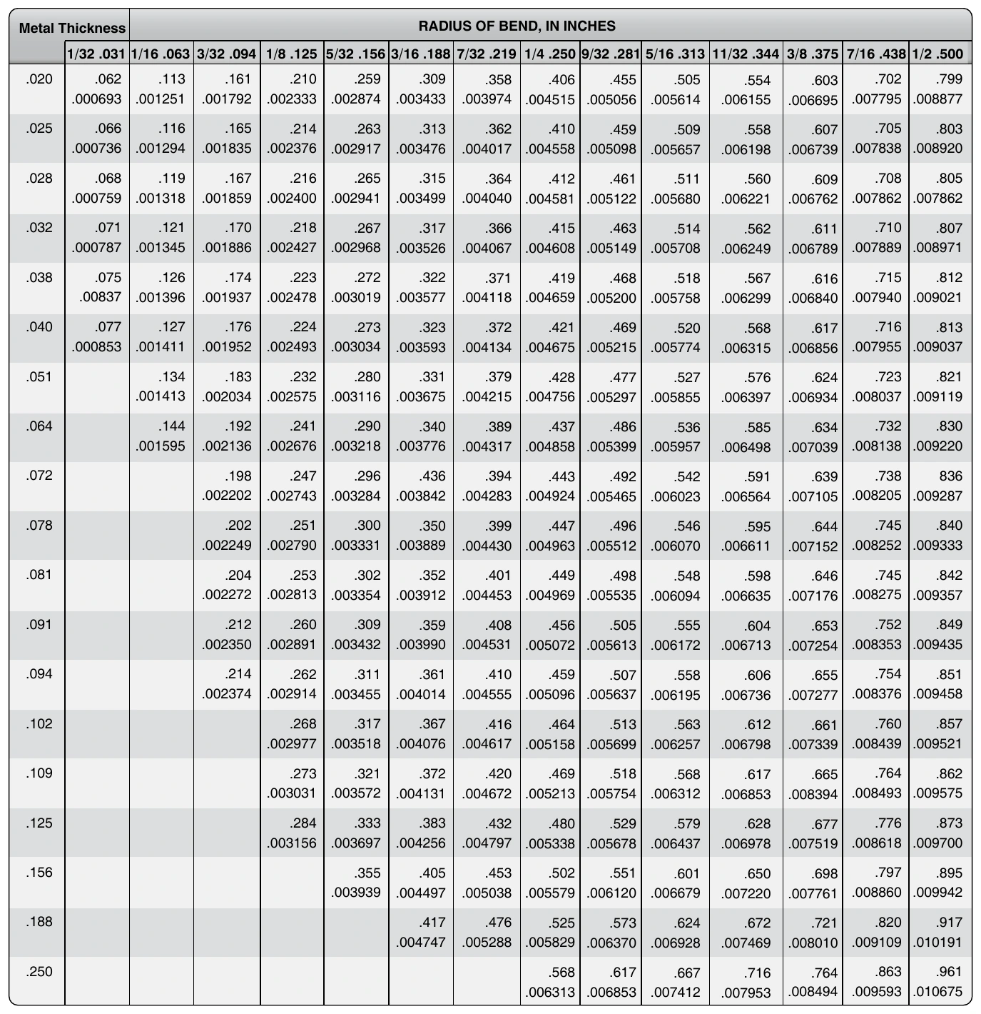
Use of Bend Allowance Chart for a 90° Bend In Figure 4-128, the radius of bend is shown on the top line, and the metal thickness is shown on the left hand column. The upper number in each cell is the bend allowance for a 90° bend. The lower number in the cell is the bend allowance per 1° of bend. To determine the bend allowance for a 90° bend, simply use the top number in the chart.
Example: The material thickness of the U-channel is 0.040-inch and the bend radius is 0.16-inch.
Reading across the top of the bend allowance chart, find the column for a radius of bend of.156-inch. Now, find the block in this column that is opposite the material thickness (gauge) of 0.040 in the column at the left. The upper number in the cell is (0.273), the correct bend allowance in inches for a 90° bends.
Several bend allowance calculation programs are available online. Just enter the material thickness, radius, and degree of bend and the computer program calculates the bend allowance.
Use of Chart for Other Than a 90° Bend If the bend is to be other than 90°, use the lower number in the block (the bend allowance for 1°) and compute the bend allowance.
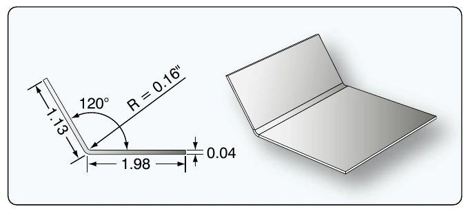
Example: The L-bracket shown in Figure 4-129 is made from 2024-T3 aluminum alloy and the bend is 60° from flat. Note that the bend angle in the figure indicates 120°, but that is the number of degrees between the two flanges and not the bend angle
Figure 4-128. Bend allowance.
Formula: Figure 4-128 formula reference: Bend-allowance lookup by metal thickness and inside bend radius. The upper value in each cell is bend allowance for a 90° bend; the lower value is bend allowance per degree for bends other than 90°. Source text: Metal Thickness RADIUS OF BEND, IN INCHES ; 1/32.031 1/16.063 3/32.094 1/8.125 5/32.156 3/16.188 7/32.219 1/4.250 9/32.281 5/16.313 11/32.344 3/8.375 7/16.438 1/2.500 ; .020.062.113.161.210.259.309.358.406.455.505.554.603.702.799 ; .000693.001251.001792.002333.002874.003433.003974.004515.005056.005614.006155.006695.007795.008877 ; .025.066.116.165.214.263.313.362.410.459.509.558.607.705.803 ; .000736.001294.001835.002376.002917.003476.004017.004558.005098.005657.006198.006739.007838.008920 ; .028.068.119.167.216.265.315.364.412.461.511.560.609.708.805 ; .000759.001318.001859.002400.002941.003499.004040.004581.005122.005680.006221.006762.007862.007862 ; .032.071.121.170.218.267.317.366.415.463.514.562.611.710.807 ; .000787.001345.001886.002427.002968.003526.004067.004608.005149.005708.006249.006789.007889.008971 ; .038.075.126.174.223.272.322.371.419.468.518.567.616.715.812 ; .00837.001396.001937.002478.003019.003577.004118.004659.005200.005758.006299.006840.007940.009021 ; .040.077.127.176.224.273.323.372.421.469.520.568.617.716.813 ; .000853.001411.001952.002493.003034.003593.004134.004675.005215.005774.006315.006856.007955.009037 ; .051.134.183.232.280.331.379.428.477.527.576.624.723.821 ; .001413.002034.002575.003116.003675.004215.004756.005297.005855.006397.006934.008037.009119 ; .064.144.192.241.290.340.389.437.486.536.585.634.732.830 ; .001595.002136.002676.003218.003776.004317.004858.005399.005957.006498.007039.008138.009220 ; .072.198.247.296.436.394.443.492.542.591.639.738 836 ; .002202.002743.003284.003842.004283.004924.005465.006023.006564.007105.008205.009287 ; .078.202.251.300.350.399.447.496.546.595.644.745.840 ; .002249.002790.003331.003889.004430.004963.005512.006070.006611.007152.008252.009333 ; .081.204.253.302.352.401.449.498.548.598.646.745.842 ; .002272.002813.003354.003912.004453.004969.005535.006094.006635.007176.008275.009357 ; .091.212.260.309.359.408.456.505.555.604.653.752.849 ; .002350.002891.003432.003990.004531.005072.005613.006172.006713.007254.008353.009435 ; .094.214.262.311.361.410.459.507.558.606.655.754.851 ; .002374.002914.003455.004014.004555.005096.005637.006195.006736.007277.008376.009458 ; .102.268.317.367.416.464.513.563.612.661.760.857 ; .002977.003518.004076.004617.005158.005699.006257.006798.007339.008439.009521 ; .109.273.321.372.420.469.518.568.617.665.764.862 ; .003031.003572.004131.004672.005213.005754.006312.006853.008394.008493.009575 ; .125.284.333.383.432.480.529.579.628.677.776.873 ; .003156.003697.004256.004797.005338.005678.006437.006978.007519.008618.009700 ; .156.355.405.453.502.551.601.650.698.797.895 ; .003939.004497.005038.005579.006120.006679.007220.007761.008860.009942 ; .188.417.476.525.573.624.672.721.820.917 ; .004747.005288.005829.006370.006928.007469.008010.009109.010191 ; .250.568.617.667.716.764.863.961 ; .006313.006853.007412.007953.008494.009593.010675
Figure 4-129. Bend allowance for bends less than 90°.
from flat. To find the correct bend angle, use the following formula:
Formula: Bend Angle = 180° – Angle between flanges
The actual bend is 60°. To find the correct bend radius for a 60° bend of material 0.040-inches thick, use the following procedure.
Go to the left side of the table and find 0.040-inch.
Go to the right and locate the bend radius of 0.16-inch (0.156-inch).
Note the bottom number in the block (0.003034).
Formula: 4. Multiply this number by the bend angle: ; 0.003034 × 60 = 0.18204
Step 5: Find the Total Developed Width of the Material
The total developed width (TDW) can be calculated when the dimensions of the flats and the bend allowance are found. The following formula is used to calculate TDW:
Formula: TDW = Flats + (bend allowance × number of bends)
We use cookies to operate this website, improve performance, understand site traffic, and personalize your experience. Essential cookies are always active because they are required for the website to function.
Required for basic site functionality and security.
Help us understand how visitors use the website so we can improve it.
May be used for advertising, remarketing, or social media features.
You can update your choices anytime using Cookie Settings. View Privacy Policy