
Chapter 7
Advanced Composite Materials
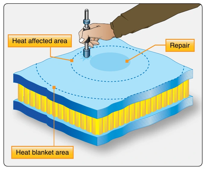
Solid Laminates
Bonded Flush Patch Repairs
New generation aircraft have fuselage and wing structures made from solid laminates that are externally stiffened with co-cured or co-bonded stringers. These solid laminates have many more plies than the face sheets of honeycomb sandwich structures. The flush repair techniques for solid laminate structures are similar for fiberglass, Kevlar®, and graphite with minor differences.
A flush repair can be stepped or, more commonly, scarved (tapered). The scarf angles are usually small to ease the load into the joint and to prevent the adhesive from escaping. This translates into thickness-to-length ratios of 1:10 to 1:70. Because inspection of bonded repairs is difficult, bonded repairs, as contrasted with bolted repairs, require a higher commitment to quality control, better trained personnel, and cleanliness.
The scarf joint is more efficient from the viewpoint of load transfer as it reduces load eccentricity by closely aligning the neutral axis of the parent and the patch. However, this configuration has many drawbacks in making the repair. First, to maintain a small taper angle, a large quantity of sound material must be removed. Second, the replacement plies must be very accurately laid up and placed in the repair joint. Third, curing of replacement plies can result in significantly reduced strength if not cured in the autoclave. Fourth, the adhesive can run to the bottom of the joint, creating a nonuniform bond line. This can be alleviated by approximating the scarf with a series of small steps. For these reasons, unless the part is lightly loaded, this type of repair is usually performed at a repair facility where the part can be inserted into the autoclave, which can result in part strength as strong as the original part.
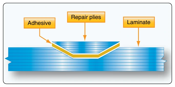
There are several different repair methods for solid laminates. The patch can be precured and then secondarily bonded to the parent material. This procedure most closely approximates the bolted repair. [Figure 7-64] The patch can be made from prepreg and then co-cured at the same time as the adhesive. The patch can also be made using a wet layup repair. The curing cycle can also vary in length of time, cure temperature, and cure pressure, increasing the number of possible repair combinations.
Scarf repairs of composite laminates are performed in the sequence of steps described below.
Step 1: Inspection & Mapping of Damage
The size and depth of damage to be repaired must be accurately surveyed using appropriate nondestructive evaluation (NDE) techniques. A variety of NDE techniques can be used to inspect for damage in composite structures. The simplest technique is visual inspection, in which whitening due to delamination and/or resin cracking can be used to indicate the damage area in semitransparent composites, such as glass-polyester and glass-vinyl ester laminates.
Visual inspection is not an accurate technique because not all damage is detectable to the eye, particularly damage hidden by paint, damage located deep below the surface, and damage in nontransparent composites, such as carbon and aramid laminates. A popular technique is tap testing, in which a lightweight object, such as a coin or hammer, is used to locate damage. The main benefits of tap testing are that it is simple and it can be used to rapidly inspect large areas. Tap testing can usually be used to detect delamination damage close to the surface, but becomes increasingly less reliable the deeper the delamination is located below the surface. Tap testing is not useful for detecting other types of damage, such as resin cracks and broken fibers.
More advanced NDE techniques for inspecting composites are impedance testing, x-ray radiography, thermography, and ultrasonics. Of these techniques, ultrasonics is arguably the most accurate and practical and is often used for surveying damage. Ultrasonics can be used to detect small delaminations located deep below the surface, unlike visual inspection and tap testing.
Step 2: Removal of Damaged Material
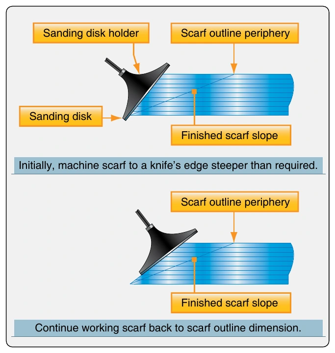
Once the scope of the damaged area to be repaired has been determined, the damaged laminate must be removed. The edges of the sound laminate are then tapered back to a shallow angle. The taper slope ratio, also known as the scarf angle, should be less than 12 to 1 (< 5°) to minimize the shear strains along the bond line after the repair patch is applied. The shallow angle also compensates for some errors in workmanship and other shop variables that might diminish patch adhesion. [Figure 7-65]
Step 3: Surface Preparation
The laminate close to the scarf zone should be lightly abraded with sandpaper, followed by the removal of dust and contaminates. It is recommended that, if the scarf zone has been exposed to the environment for any considerable period of time, it should be cleaned with a solvent to remove contamination.
Step 4: Molding
A rigid backing plate having the original profile of the composite structure is needed to ensure the repair has the same geometry as the surrounding structure.