
Chapter 9
Aircraft Electrical System
AC Supply
Many modern light aircraft employ a low-power AC electrical system. Commonly, the AC system is used to power certain instruments and some lighting that operate only using AC. The electroluminescent panel has become a popular lighting system for aircraft instrument panels and requires AC. Electroluminescent lighting is very efficient and lightweight; therefore, excellent for aircraft installations. The electroluminescent material is a paste-like substance that glows when supplied with a voltage. This material is typically molded into a plastic panel and used for lighting.
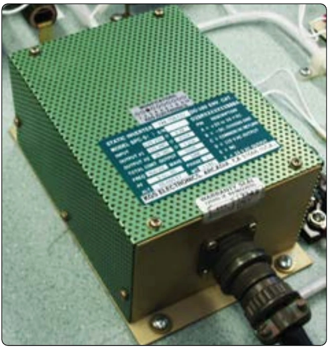
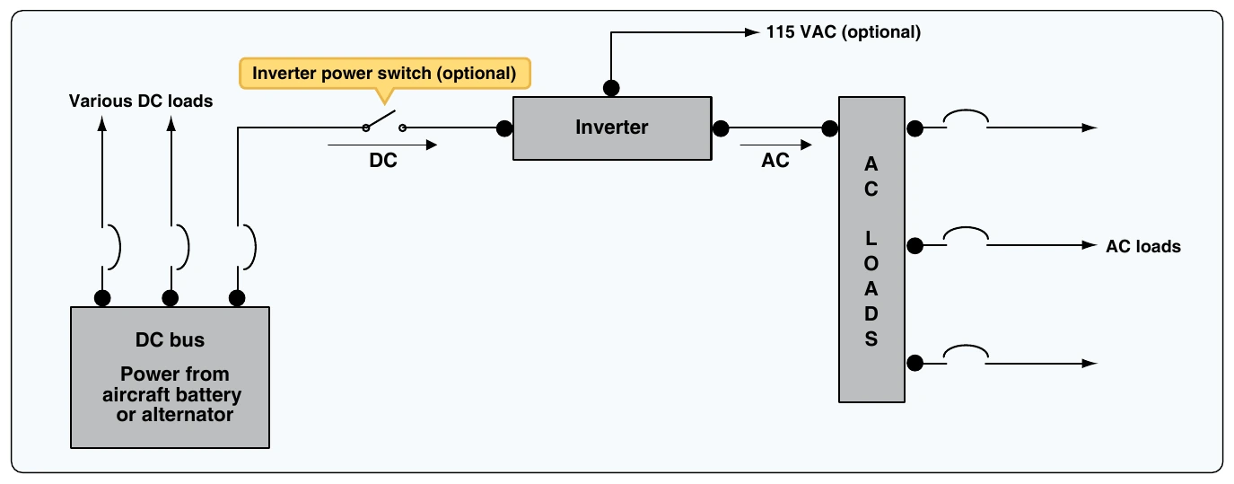
Adevice called an inverter is used to supply AC when needed for light aircraft. Simply put, the inverter changes DC into AC. Two types of inverters may be found on aircraft: rotary inverters and static inverters. Rotary inverters are found only on older aircraft due to its poor reliability, excess weight, and inefficiency. The rotary inverters employee a DC motor that spins an AC generator. The unit is typically one unit and contains a voltage regulator circuit to ensure voltage stability. Most aircraft have a modern static inverter instead of a rotary inverter. Static inverters, as the name implies, contain no moving parts and use electronic circuitry to convert DC to AC. Figure 9-98 shows a static inverter. Whenever AC is used on light aircraft, a distribution circuit separated from the DC system must be employed. [Figure 9-99]
Some aircraft use an inverter power switch to control AC power. Many aircraft simply power the inverter whenever the DC bus is powered and no inverter power switch is needed. On complex aircraft, more than one inverter may be used to provide a backupAC power source. Many inverters also offer more than one voltage output. Two common voltages found on aircraft inverters are 26VAC and 115VAC.
Light Multiengine Aircraft
Multiengine aircraft typically fly faster, higher, and farther than single engine aircraft. Multiengine aircraft are designed for added safety and redundancy and, therefore, often contain a more complex power distribution system when compared to light single-engine aircraft. With two engines, these aircraft can drive two alternators (or generators) that supply current to the various loads of the aircraft. The electrical distribution bus system is also divided into two or more systems. These bus systems are typically connected through a series of circuit protectors, diodes, and relays. The bus system is designed to create a power distribution system that is extremely reliable by supplying current to most loads through more than one source.
Paralleling Alternators or Generators
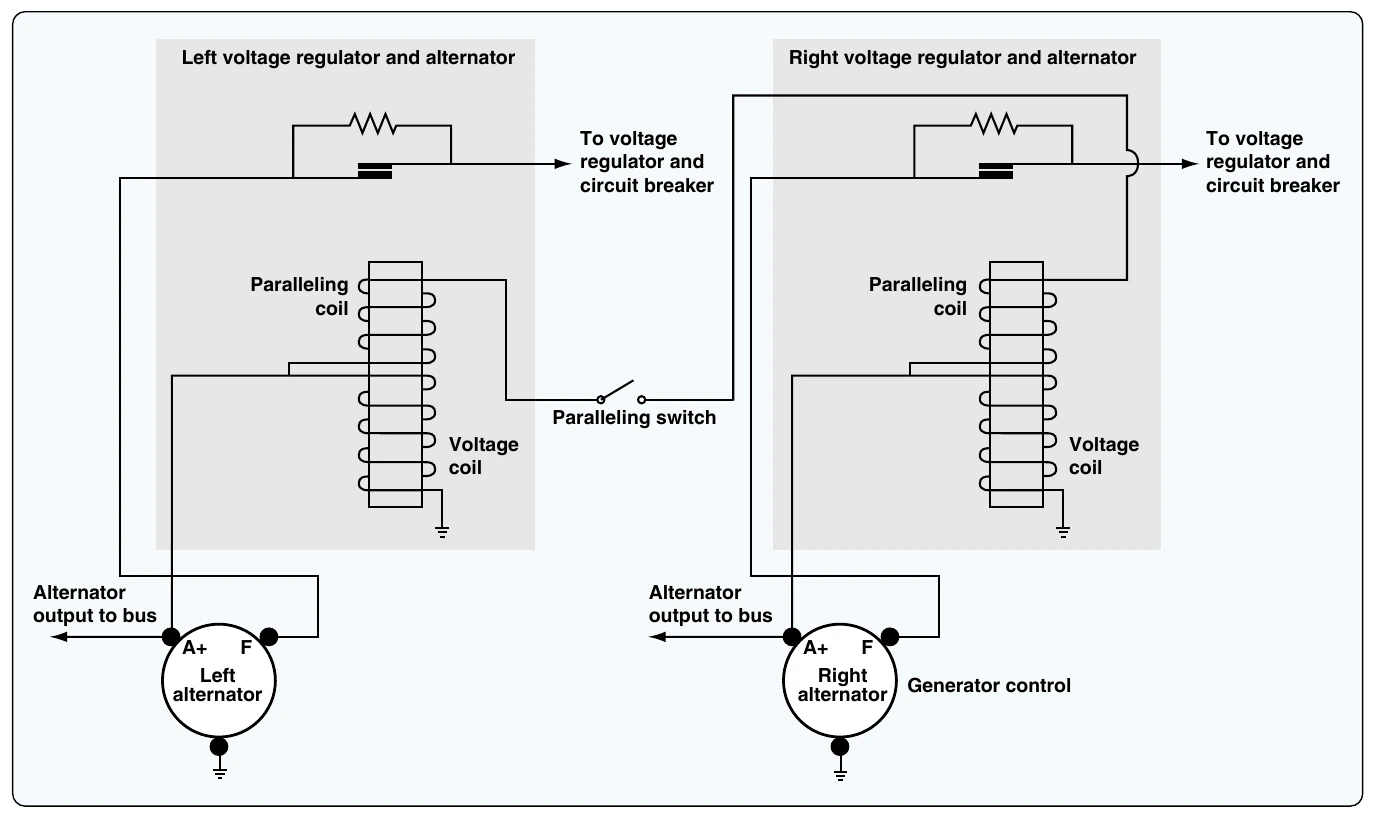
Since two alternators (or generators) are used on twin engine aircraft, it becomes vital to ensure both alternators share the electrical load equally. This process of equalizing alternator outputs is often called paralleling. In general, paralleling is a simple process when dealing with DC power systems found on light aircraft. If both alternators are connected to the same load bus and both alternators produce the same output voltage, the alternators share the load equally. Therefore, the paralleling systems must ensure both power producers maintain system voltage within a few tenths of a volt. For most twin-engine aircraft, the voltage would be between 26.5-volt and 28-volt DC with the alternators operating. A simple vibrating point system used for paralleling alternators is found in Figure 9-100.
As can be seen in Figure 9-100, both left and right voltage regulators contain a paralleling coil connected to the output of each alternator. This paralleling coil works in conjunction with the voltage coil of the regulator to ensure proper alternator output. The paralleling coils are wired in series between the output terminals of both alternators. Therefore, if the two alternators provide equal voltages, the paralleling coil has no effect. If one alternator has a higher voltage output, the paralleling coils create the appropriate magnetic force to open/close the contact points, controlling field current and control alternator output.
Today’s aircraft employ solid-state control circuits to ensure proper paralleling of the alternators. Older aircraft use vibrating point voltage regulators or carbon-pile regulators to monitor and control alternator output. For the most part, all carbon-pile regulators have been replaced except on historic aircraft. Many aircraft still maintain a vibrating point system, although these systems are no longer being used on contemporary aircraft. The different types of voltage regulators were described earlier in this chapter.
Power Distribution on Multiengine Aircraft
The power distribution systems found on modern multiengine aircraft contain several distribution points (buses) and a variety of control and protection components to ensure the reliability of electrical power. As aircraft employ more electronics to perform various tasks, the electrical power systems becomes more complex and more reliable. One means to increase reliability is to ensure more than one power source can be used to power any given load. Another important design concept is to supply critical electrical loads from more than one bus. Twin-engine aircraft, such as a typical corporate jet or commuter aircraft, have two DC generators; they also have multiple distribution buses fed from each generator. Figure 9-101 shows a simplified diagram of the power distribution system for a twin-engine turboprop aircraft.
This aircraft contains two starter generator units used to start the engines and generate DC electrical power. The system is typically defined as a split-bus power distribution system since there is a left and right generator bus that splits (shares) the electrical loads by connecting to each sub-bus through a diode and current limiter. The generators are operated in parallel and equally carry the loads.
The primary power supplied for this aircraft is DC, although small amounts of AC are supplied by two inverters. The aircraft diagram shows the AC power distribution at the top and mid left side of the diagram. One inverter is used for main AC power and the second is operated in standby and ready as a backup. Both inverters produce 26-volt AC and 115-volt AC. There is an inverter select relay operated by a pilot controlled switch used to choose which inverter is active.
The hot battery bus (right side of Figure 9-101) shows a direct connection to the aircraft battery. This bus is always hot if there is a charged battery in the aircraft. Items powered by this bus may include some basics like the entry door lighting and the aircraft clock, which should always have power available. Other items on this bus would be critical to flight safety, such as fire extinguishers, fuel shutoffs, and fuel pumps. During a massive system failure, the hot battery bus is the last bus on the aircraft that should fail.