Chapter 9
Aircraft Electrical System
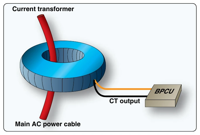
A CT is an inductive unit that surrounds the main power cables of the electrical distribution system. As AC power flows through the main cables, the CT receives an induced voltage. The amount of CT voltage is directly related to the current flowing through the cable. The CT connects to the BPCU, which allows accurate current monitoring of the system. A typical aircraft employs several CTs throughout the electrical system.
The BPCU is a dedicated computer that controls the electrical connections between the various distribution buses found on the aircraft. The BPCU uses contactors (solenoids) called bus tie breakers (BTB) for connection of various circuits. These BTBs open/close the connections between the buses as needed for system operation as called for by the pilots and the BPCU. This sounds like a simple task, yet to ensure proper operation under a variety of conditions, the bus system becomes very complex. There are three common types of distribution bus systems found on transport category aircraft: split bus, parallel bus, and split parallel.
Split-Bus Power Distribution Systems
Modern twin-engine aircraft, such as the Boeing 737, 757, 777, Airbus A-300, A-320, and A-310, employ a split-bus power distribution system. During normal conditions, each engine-driven AC generator powers only one main AC bus. The buses are kept split from each other, and two generators can never power the same bus simultaneously. This is very important since the generator output current is not phase regulated. (If two out-of-phase generators were connected to the same bus, damage to the system would occur.) The split-bus system does allow both engine-driven generators to power any given bus, but not at the same time. Generators must remain isolated from each other to avoid damage. The GCUs and BPCU ensures proper generator operation and power distribution.
On all modern split bus systems, the APU can be started and operated during flight. This allows the APU generator to provide back-up power in the event of a main generator failure. A fourth emergency generator powered by the ram air turbine is also available if the other generators fail.
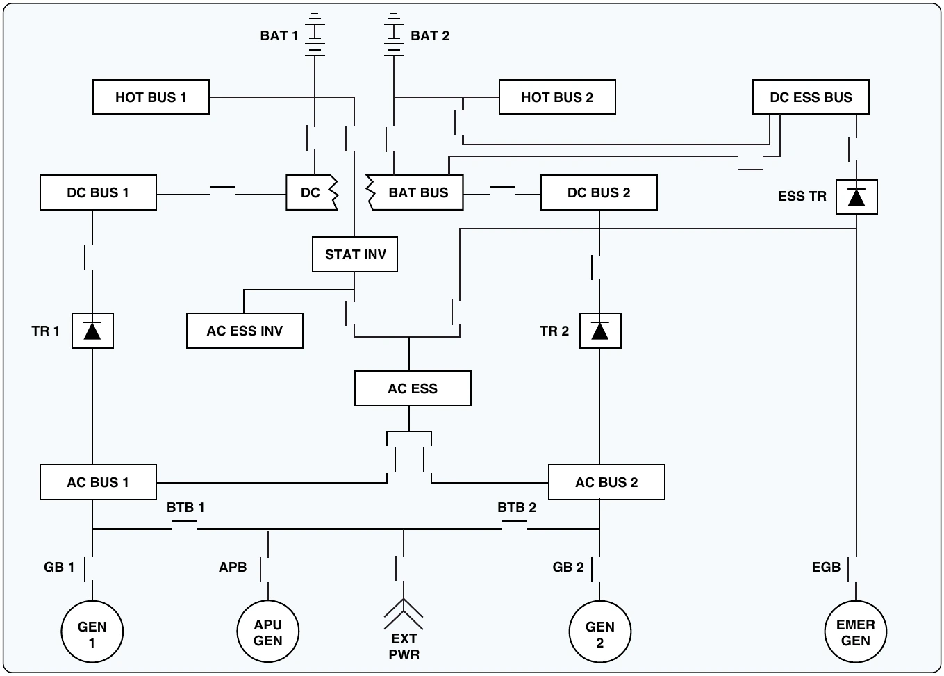
The four AC generators are shown at the bottom of
respective buses through the generator breakers. For example, generator 1 sends current through GB1 to AC bus 1. AC bus 1 feeds a variety of primary electrical loads, and also feeds sub-buses that in turn power additional loads.
With both generators operating and all systems normal, AC bus 1 and AC bus 2 are kept isolated. Typically during flight, the APB (bottom center of Figure 9-104) would be open and the APU generator off; the emergency generator (bottom right) would also be off and disconnected. If generator one should fail, the following happens:
- The GB 1 is opened by the GCU to disconnect the failed generator.
- The BPCU closes BTB 1 and BTB 2. This supplies AC power to AC bus 1 from generator 2.
- The pilots start the APU and connect the APU generator. At that time, the BPCU and GCUs move the appropriate BTBs to correctly configure the system so the APU powers bus 1 and generator 2 powers bus 2. Once again, two AC generators operate independently to power AC bus 1 and 2.
If all generators fail, AC is also available through the static inverter (center of Figure 9-104). The inverter is powered from the hot battery bus and used for essential AC loads if all AC generators fail. Of course, the GCUs and BPCU take the appropriate actions to disconnect defective units and continue to feed essential AC loads using inverter power.
To produce DC power, AC bus 1 sends current to its transformer rectifier (TR), TR 1 (center left of Figure 9-104). The TR unit is used to change AC to DC. The TR contains a transformer to step down the voltage from 115-volt AC to 26-volt AC and a rectifier to change the 26-volt AC to 26-volt DC. The output of the TR is therefore compatible with the aircraft battery at 26-volt DC. Since DC power is not phase sensitive, the DC buses are connected during normal operation. In the event of a bus problem, the BPCU may isolate one or more DC buses to ensure correct distribution of DC power. This aircraft contains two batteries that are used to supply emergency DC power.
Parallel Systems
Multiengine aircraft, such as the Boeing 727, MD-11, and the early Boeing 747, employ a parallel power distribution system. During normal flight conditions, all engine-driven generators connect together and power the AC loads. In this configuration, the generators are operated in parallel; hence the name parallel power distribution system. In a parallel system, all generator output current must be phase regulated.
Before generators are connected to the same bus, their output frequency must be adjusted to ensure the AC output reaches the positive and negative peaks simultaneously. During the flight, generators must maintain this in-phase condition for proper operation.
One advantage of parallel systems is that in the event of a generator failure, the buses are already connected and the defective generator need only be isolated from the system. A paralleling bus, or synchronizing bus, is used to connect the generators during flight. The synchronizing bus is often referred to as the sync bus. Most of these systems are less automated and require that flight crew monitor systems and manually control bus contactors. BTBs are operated by the flight crew through the electrical control panel and used to connect all necessary buses. GBs are used to connect and disconnect the generators.
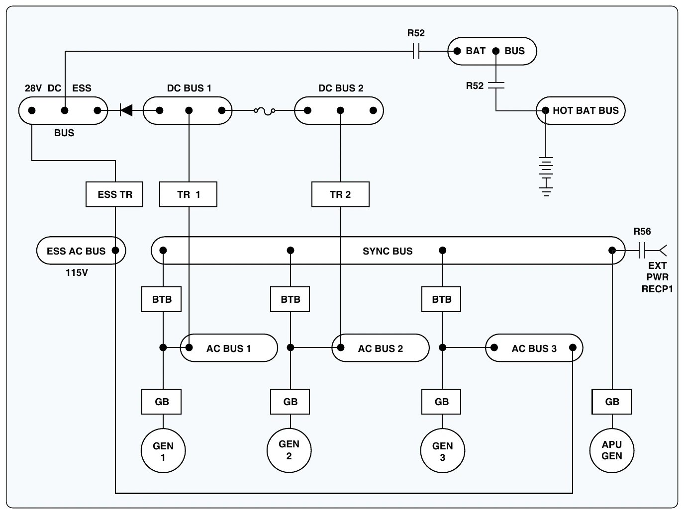
Figure 9-105 shows a simplified parallel power distribution system. This aircraft employs three main-engine driven generators and one APU generator. The APU (bottom right) is not operational in flight and cannot provide backup power. The APU generator is for ground operations only. The three main generators (bottom of Figure 9-105) are connected to their respective AC bus through GBs one, two, and three. The AC buses are connected to the sync bus through three BTBs. In this manner, all three generators share the entire AC electrical loads. Keep in mind, all generators connected to the sync bus must be in phase. If a generator fails, the flight crew would simply isolate the defective generator and the flight would continue without interruption.
The number one and two DC buses (Figure 9-105 top left) are used to feed the DC electrical loads of the aircraft. DC bus 1 receives power form AC bus 1 though TR1. DC bus 2 is fed in a similar manner from AC bus 2. The DC buses also connect to the battery bus and eventually to the battery. The essential DC bus (top left) can be fed from DC bus 1 or the essential TR. A diode prevents the essential DC bus from powering DC bus 1. The essential DC bus receives power from the essential TR, which receives power from the essential AC bus. This provides an extra layer of redundancy since the essential AC bus can be isolated and fed from any main generator. Figure 9-105 shows generator 3 powering the essential AC bus.