
Chapter 9
Aircraft Electrical System
If the battery switch is closed and the battery relay activated, battery power is connected to the main battery bus and the isolation bus. The main battery bus carries current for engine starts and external power. So the main battery bus must be large enough to carry the heaviest current loads of the aircraft. It is logical to place this bus as close as practical to the battery and starters and to ensure the bus is well protected from shorts to ground.
The isolation bus connects to the left and right buses and receives power whenever the main battery bus is energized. The isolation bus connects output of the left and right generators in parallel. The output of the two generators is then sent to the loads through additional buses. The generator buses are connected to the isolation bus through a fuse known as a current limiter. Current limiters are high amperage fuses that isolate buses if a short circuit occurs. There are several current limiters used in this system for protection between buses. As can be seen in Figure 9-101, a current limiter symbol looks like two triangles pointed toward each other. The current limiter between the isolation bus and the main generator buses are rated at 325 amps and can only be replaced on the ground. Most current limiters are designed for ground replacement only and only after the malfunction that caused the excess current draw is repaired.
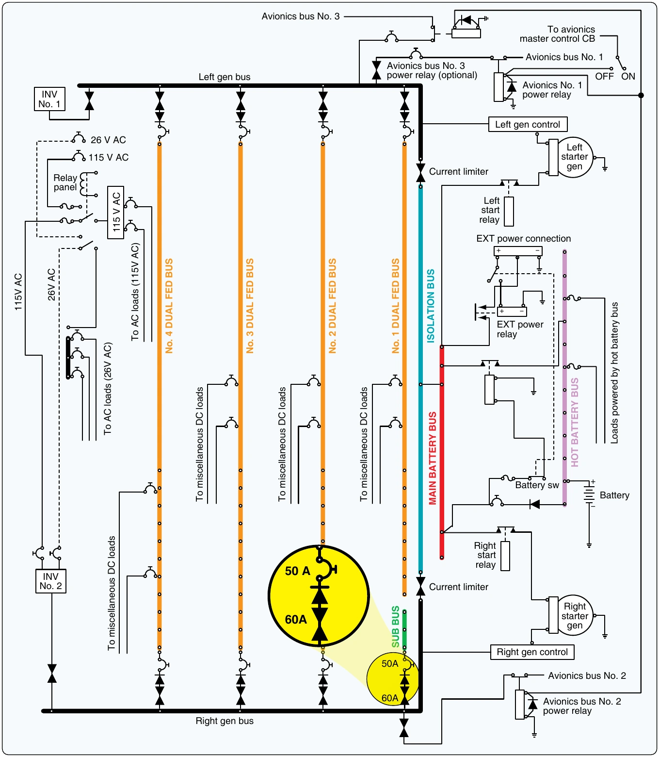
The left and right DC generators are connected to their respective main generator buses. Each generator feeds its respective bus, and since the buses are connected under normal circumstances, the generators operate in parallel.
Both generators feed all loads together. If one generator fails or a current limiter opens, the generators can operate independently. This design allows for redundancy in the event of failure and provides battery backup in the event of a dual generator failure.
In the center of Figure 9-101 are four dual-feed electrical buses. These buses are considered dual-feed since they receive power from both the left and right generator buses. If a fault occurs, either generator bus can power any or all loads on a dual-feed bus. During the design phase of the aircraft, the electrical loads must be evenly distributed between each of the dual-feed buses. It is also important to power redundant systems from different buses. For example, the pilot’s windshield heat would be powered by a different bus from the one that powers the copilot’s windshield heat. If one bus fails, at least one windshield heat continues to work properly, and the aircraft can be landed safely in icing conditions.
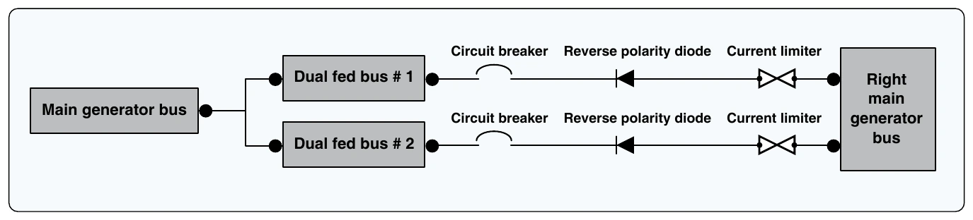
Notice that the dual-feed buses are connected to the main generator buses through both a current limiter and a diode. Remember, a diode allows current flow in only one direction. [Figure 9-102]
The current can flow from the generator bus to the dual-feed bus, but the current cannot flow from the dual fed bus to the main generator bus. The diode is placed in the circuit so the main bus must be more positive than the sub bus for current flow. This circuit also contains a current limiter and a circuit breaker. The circuit breaker is located on the flight deck and can be reset by the pilot. The current limiter can only be replaced on the ground by a technician. The circuit breaker is rated at a slightly lower current value than the current limiter; therefore, the circuit breaker should open if a current overload exists. If the circuit breaker fails to open, the current limiter provides backup protection and disconnects the circuit.
Large Multiengine Aircraft
Transport category aircraft typically carry hundreds of passengers and fly thousands of miles each trip. Therefore, large aircraft require extremely reliable power distribution systems that are computer controlled. These aircraft have multiple power sources (AC generators) and a variety of distribution buses. A typical airliner contains two or more main AC generators driven by the aircraft turbine engines, as well as more than one backup AC generator. DC systems are also employed on large aircraft and the ship’s battery is used to supply emergency power in case of a multiple failures.
The AC generator (sometimes called an alternator) produces three-phase 115-volt AC at 400 Hz. AC generators were discussed previously in this chapter. Since most modern transport category aircraft are designed with two engines, there are two main AC generators. The APU also drives an AC generator. This unit is available during flight if one of the main generators fails. The main and auxiliary generators are typically similar in output capacity and supply a maximum of 110 kilovolt amps (KVA). A fourth generator, driven by an emergency ram air turbine, is also available in the event the two main generators and one auxiliary generator fail. The emergency generator is typically smaller and produces less power. With four AC generators available on modern aircraft, it is highly unlikely that a complete power failure occurs. However, if all AC generators are lost, the aircraft battery will continue to supply DC electrical power to operate vital systems.
AC Power Systems
Transport category aircraft use large amounts of electrical power for a variety of systems. Passenger comfort requires power for lighting, audio visual systems, and galley power for food warmers and beverage coolers. A variety of electrical systems are required to fly the aircraft, such as flight control systems, electronic engine controls, communication, and navigation systems. The output capacity of one engine-driven AC generator can typically power all necessary electrical systems. A second engine-driven generator is operated during flight to share the electrical loads and provide redundancy.
The complexity of multiple generators and a variety of distribution buses requires several control units to maintain a constant supply of safe electrical power. The AC electrical system must maintain a constant output of 115 to 120 volts at
power limits are not exceeded. AC generators are connected to the appropriate distribution buses at the appropriate time, and generators are in phase when needed. There is also the need to monitor and control any external power supplied to the aircraft, as well as control of all DC electrical power.
Two electronic line replaceable units are used to control the electrical power on a typical large aircraft. The generator control unit (GCU) is used for control of AC generator functions, such as voltage regulation and frequency control. The bus power control unit (BPCU) is used to control the distribution of electrical power between the various distribution buses on the aircraft. The GCU and BPCU work together to control electrical power, detect faults, take corrective actions when needed, and report any defect to the pilots and the aircraft’s central maintenance system. There is typically one GCU for each AC generator and at least one BPCU to control bus connections. These LRUs are located in the aircraft’s electronics equipment bay and are designed for easy replacement.
When the pilot calls for generator power by activating the generator control switch on the flight deck, the GCU monitors the system to ensure correct operation. If all systems are operating within limits, the GCU energizes the appropriate generator circuits and provides voltage regulation for the system. The GCU also monitors AC output to ensure a constant 400-Hz frequency. If the generator output is within limits, the GCU then connects the electrical power to the main generator bus through an electrical contactor (solenoid). These contactors are often called generator breakers (GB) since they break (open) or make (close) the main generator circuit.
After generator power is available, the BPCU activates various contactors to distribute the electrical power. The BPCU monitors the complete electrical system and communicates with the GCU to ensure proper operation. The BPCU employs remote current sensors known as a current transformers (CT) to monitor the system. [Figure 9-103]