
Chapter 9
Aircraft Electrical System
size using Figure 9-116, the following must be known:
- The wire length in feet.
- The number of amperes of current to be carried.
- The allowable voltage drop permitted.
- The required continuous or intermittent current.
- The estimated or measured conductor temperature.
- Is the wire to be installed in conduit and/or bundle?
- Is the wire to be installed as a single wire in free air?
Example A Find the wire size in Figure 9-116 using the following known information:
- The wire run is 50 feet long, including the ground wire.
- Current load is 20 amps.
- The voltage source is 28 volts from bus to equipment.
- The circuit has continuous operation.
- Estimated conductor temperature is 20 °C or less. The scale on the left of the chart represents maximum wire length in feet to prevent an excessive voltage drop for a specified voltage source system (e.g., 14V, 28V, 115V, 200V). This voltage is identified at the top of scale and the corresponding voltage drop limit for continuous operation at the bottom. The scale (slant lines) on top of the chart represents amperes. The scale at the bottom of the chart represents wire gauge.
Step 1—From the left scale, find the wire length 50 feet under the 28V source column.
Step 2—Follow the corresponding horizontal line to the right until it intersects the slanted line for the 20-amp load.
Step 3—At this point, drop vertically to the bottom of the chart. The value falls between No. 8 and No. 10. Select the next larger size wire to the right, in this case No. 8. This is the smallest size wire that can be used without exceeding the voltage drop limit expressed at the bottom of the left scale. This example is plotted on the wire chart in
and Figure 9-116 (bottom) for intermittent flow.
Example B Find the wire size in Figure 9-116 using the following known information:
- The wire run is 200 feet long, including the ground wire.
- Current load is 10 amps.
- The voltage source is 115 volts from bus to equipment.
- The circuit has intermittent operation.
Step 1—From the left scale, find the wire length of 200 feet under the 115V source column.
Step 2—Follow the corresponding horizontal line to the right until it intersects the slanted line for the 10-amp load.
Step 3—At this point, drop vertically to the bottom of the chart. The value falls between No. 16 and No. 14. Select the next larger size wire to the right—in this case, No. 14. This is the smallest size wire that can be used without exceeding the voltage drop limit expressed at the bottom of the left scale.
Wire Identification
The proper identification of electrical wires and cables with their circuits and voltages is necessary to provide safety of operation, safety to maintenance personnel, and ease of maintenance. All wire used on aircraft must have its type identification imprinted along its length. It is common practice to follow this part number with the five digit/letter Commercial and Government Entity (CAGE) code identifying the wire manufacturer. You can identify the performance capabilities of existing installed wire you need to replace, and avoid the inadvertent use of a lower performance and unsuitable replacement wire.
Placement of Identification Markings
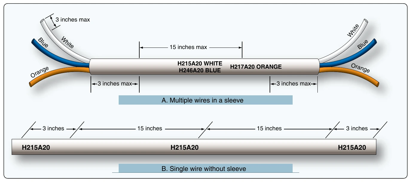
Identification markings should be placed at each end of the wire and at 15-inch maximum intervals along the length of the wire. Wires less than 3 inches in length need not be identified. Wires 3 to 7 inches in length should be identified approximately at the center. Added identification marker sleeves should be located so that ties, clamps, or supporting devices need not be removed to read the identification. The wire identification code must be printed to read horizontally (from left to right) or vertically (from top to bottom). The two methods of marking wire or cable are as follows:
- Direct marking is accomplished by printing the cable’s outer covering. [Figure 9-124B]
- Indirect marking is accomplished by printing a heat-shrinkable sleeve and installing the printed sleeve on the wire or cables outer covering. Indirectly-marked wire or cable should be identified with printed sleeves at each end and at intervals not longer than 6 feet. [Figure 9-125] The individual wires inside a cable should be identified within 3 inches of their termination. [Figure 9-124A]