Chapter 9
Aircraft Electrical System
Step 4—Refer to the altitude derating curve of Figure 9-119, look for sea level and 20,000 feet (on the horizontal axis) since these are the conditions at which the load is carried. The wire must be derated by a factor of 1.0 and 0.91, respectively.
Step 5—Derate the size 12 in a bundle ratings by multiplying 29.2 amps at sea level and 25.4 amps at 20,000 feet by 1.0 and 0.91, respectively to obtain 29.2 amps and 23.1 amps.
at 20,000 feet and 60 °C ambient temperature.
Step 6—Determine the actual circuit current for each wire in the bundle and for the bundle. If the values calculated in Step 5 are exceeded, select the next larger size wire and repeat the calculations.
Allowable Voltage Drop
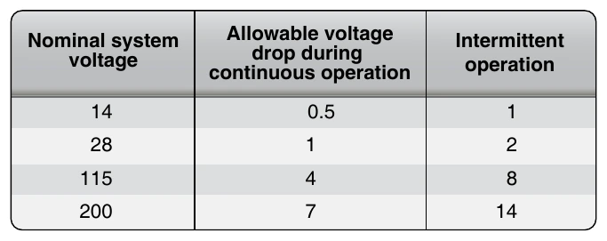
The voltage drop in the main power wires from the generation source or the battery to the bus should not exceed 2 percent of the regulated voltage when the generator is carrying rated current or the battery is being discharged at the 5-minute rate. The tabulation shown in Figure 9-121 defines the maximum acceptable voltage drop in the load circuits between the bus and the utilization equipment ground.
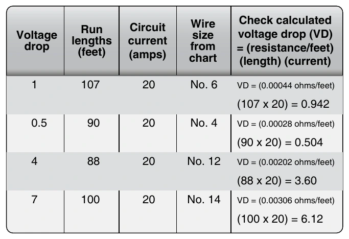
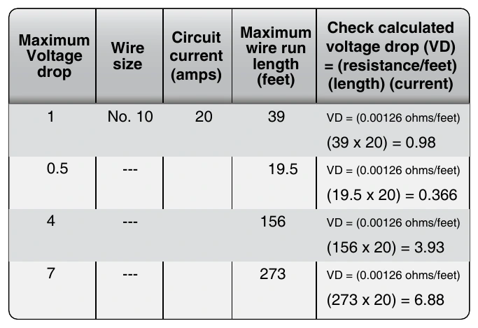
The resistance of the current return path through the aircraft structure is generally considered negligible. However, this is based on the assumption that adequate bonding to the structure or a special electric current return path has been provided that is capable of carrying the required electric current with a negligible voltage drop. To determine circuit resistance, check the voltage drop across the circuit. If the voltage drop does not exceed the limit established by the aircraft or product manufacturer, the resistance value for the circuit may be considered satisfactory. When checking a circuit, the input voltage should be maintained at a constant value. Figures 9-122 and 9-123 show formulas that may be used to determine electrical resistance in wires and some typical examples.
The following formula can be used to check the voltage drop. The resistance/ft can be found in Figures 9-122 and 9-123 for the wire size.
Electric Wire Chart Instructions
To select the correct size of electrical wire, two major requirements must be met:
- The wire size should be sufficient to prevent an excessive voltage drop while carrying the required current over the required distance. [Figure 9-121]
- The size should be sufficient to prevent overheating of the wire carrying the required current. (See Maximum Operating Temperature earlier in this chapter for computing current carrying capacity methods.)
To meet the two requirements for selecting the correct wire