
Chapter 9
Aircraft Electrical System
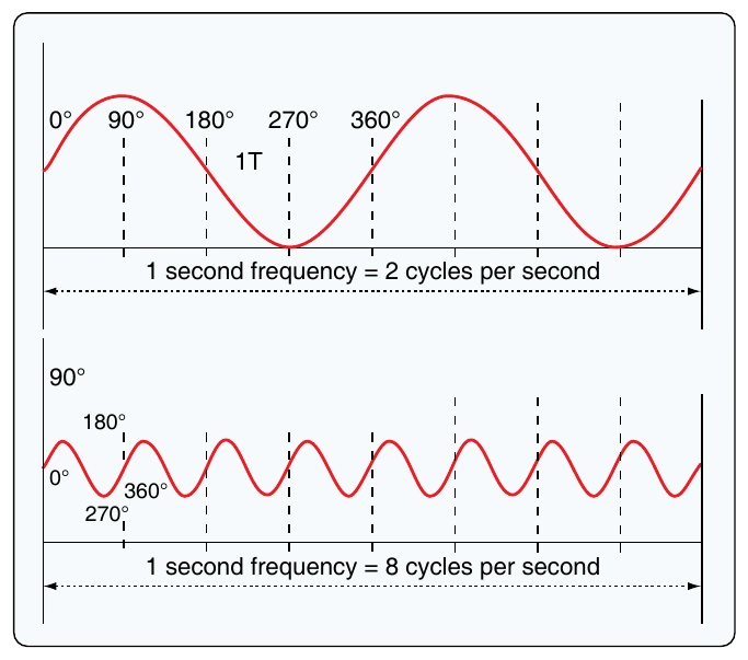
How often the AC waveform repeats is known as the AC frequency. The frequency is typically measured in cycles per second (CPS) or hertz (Hz). One Hz equals one CPS. The time it takes for the sine wave to complete one cycle is known as period (P). Period is a value or time period and typically measured in seconds, milliseconds, or microseconds. It should be noted that the time period of a cycle can change from one system to another; it is always said that the cycle completes in 360° (related to the 360° of rotation of an AC alternator). [Figure 9-13]
Cycle Defined
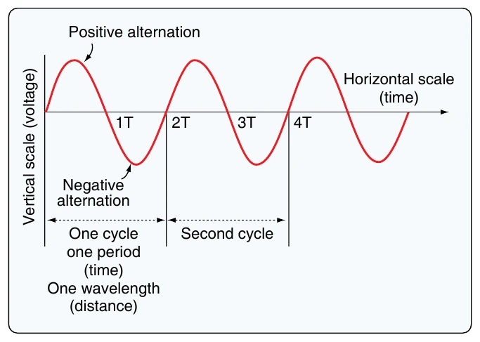
A cycle is a completion of a pattern. Whenever a voltage or current passes through a series of changes, returns to the starting point, and then repeats the same series of changes, the series is called a cycle. When the voltage values are graphed, as in Figure 9-14, the complete AC cycle is displayed. One complete cycle is often referred to as the sine wave and said to be 360°. It is typical to start the sine wave where the voltage is zero. The voltage then increases to a maximum positive value, decreases to a value of zero, then increases to a maximum negative value, and again decreases to zero. The cycle repeats until the voltage is no longer available. There are two alternations in a complete cycle: the positive alternation and the negative. It should be noted that the polarity of the voltage reverses for each half cycle. Therefore, during the positive half cycle, the electron flow is considered to be in one direction; during the negative half cycle, the electrons reverse direction and flow the opposite way through the circuit.
Frequency Defined
The frequency is the number of cycles of AC per second (CPS). The standard unit of frequency measurement is the Hz. [Figure 9-15] In a generator, the voltage and current pass through a complete cycle of values each time a coil or conductor passes under a north and south pole of the magnet. The number of cycles for each revolution of the coil or conductor is equal to the number of pairs of poles. The frequency, then, is equal to the number of cycles in one revolution multiplied by the number of revolutions per second.
Period Defined
The time required for a sine wave to complete one full cycle is called a period (P). A period is typically measured in seconds, milliseconds, or microseconds. [Figure 9-14] The period of a sine wave is inversely proportional to the frequency. That is to say that the higher the frequency, the shorter the period. The mathematical relationship between frequency and period is given as:
Wavelength Defined
The distance that a waveform travels during a period is commonly referred to as a wavelength and is indicated by the Greek letter lambda (λ). Wavelength is related to frequency by the formula:
The higher the frequency is, the shorter the wavelength is. The measurement of wavelength is taken from one point on the waveform to a corresponding point on the next waveform. [Figure 9-14] Since wavelength is a distance, common units of measure include meters, centimeters, millimeters, or nanometers. For example, a sound wave of
the actual wavelength depends on the media through which the waveform must travel.
Phase Relationships
Phase is the relationship between two sine waves, typically measured in angular degrees. For example, if there are two different alternators producing power, it would be easy to compare their individual sine waves and determine their phase relationship. In Figure 9-16B, there is a 90° phase difference between the two voltage waveforms. A phase relationship can be between any two sine waves. The phase relationship can be measured between two voltages of different alternators or the current and voltage produced by the same alternator.
Figure 9-16A shows a voltage signal and a current signal superimposed on the same time axis. Notice that when the voltage increases in the positive alternation that the current also increases. When the voltage reaches its peak value, so does the current. Both waveforms then reverse and decrease back to a zero magnitude, then proceed in the same manner in the negative direction as they did in the positive direction. When two waves are exactly in step with each other, they are said to be in phase. To be in phase, the two waveforms must go through their maximum and minimum points at the same time and in the same direction.