
Chapter 9
Aircraft Electrical System
In Figure 9-18, an AC series circuit is shown in which the inductance is 0.146 henry and the voltage is 110 volts at a frequency of 60 cycles per second. Inductive reactance is determined by the following method.
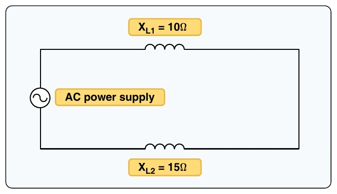
In AC series circuits, inductive reactance is added like resistances in series in a DC circuit. [Figure 9-19] The total reactance in the illustrated circuit equals the sum of the individual reactances.
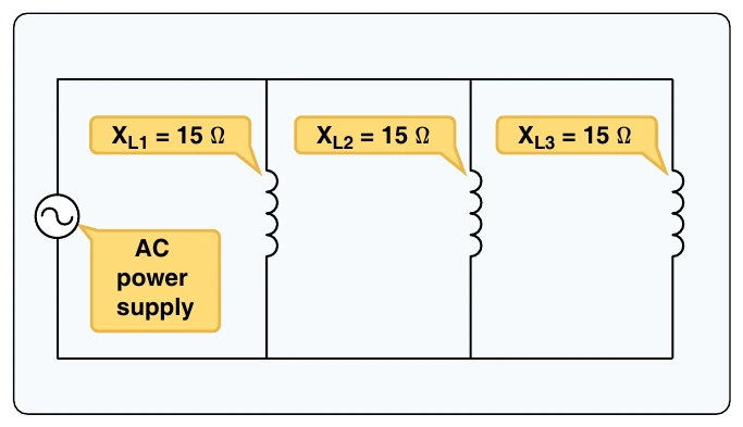
The total reactance of inductors connected in parallel is found the same way as the total resistance in a parallel circuit. [Figure 9-20] Thus, the total reactance of inductances connected in parallel, as shown, is expressed as:
Capacitive Reactance
Capacitance is the ability of a body to hold an electric charge. In general, a capacitor is constructed of two parallel plates separated by an insulator. The insulator is commonly called the dielectric. The capacitor’s plates have the ability to store electrons when charged by a voltage source. The capacitor discharges when the applied voltage is no longer present and the capacitor is connected to a current path. In an electrical circuit, a capacitor serves as a reservoir or storehouse for electricity.
The basic unit of capacitance is the farad and is given by the letter F. By definition, one farad is one coulomb of charge stored with one volt across the plates of the capacitor. In practical terms, one farad is a large amount of capacitance. Typically, in electronics, much smaller units are used. The two more common smaller units are the microfarad (μF), which is 10-6 farad and the picofarad (pF), which is 10-12 farad.
Capacitance is a function of the physical properties of the capacitor:
- The capacitance of parallel plates is directly proportional to their area. Alarger plate area produces a larger capacitance, and a smaller area produces less capacitance. If we double the area of the plates, there is room for twice as much charge.
- The capacitance of parallel plates is inversely proportional to the distance between the plates.
- The dielectric material effects the capacitance of parallel plates. The dielectric constant of a vacuum is defined as 1, and that of air is very close to 1. These values are used as a reference, and all other materials have values relative to that of air (vacuum).
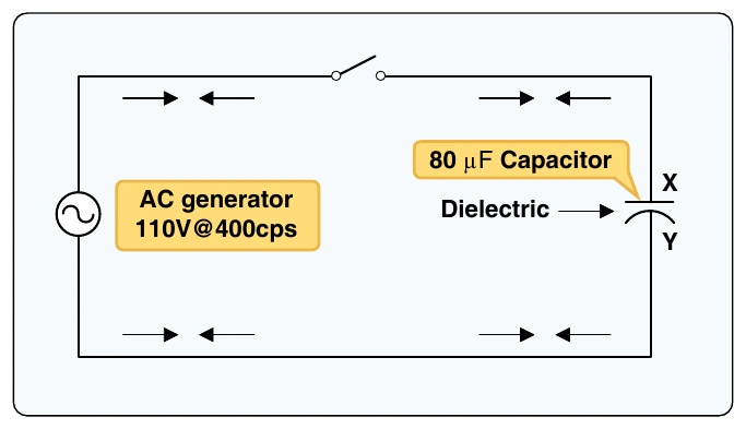
When an AC is applied in the circuit, the charge on the plates constantly changes. [Figure 9-21] This means that electricity must flow first from Y clockwise around to X, then from X counterclockwise around to Y, then from Y clockwise around to X, and so on. Although no current flows through the insulator between the plates of the capacitor, it constantly flows in the remainder of the circuit between X and Y. As this current alternates to and from the capacitor, a certain time lag is created. When a capacitor charges or discharges through a resistance, a certain amount of time is required for a full charge or discharge. The voltage across the capacitor does not change instantaneously. The rate of charging or discharging is determined by the time constant of the circuit. This rate of charge and discharge creates an opposition to current flow in AC circuits known as capacitive reactance. Capacitive reactance is symbolized by XC and is measured in ohms. This characteristic of a capacitor may also create a phase shift between voltage and current of the circuit. The phase shift created by capacitive reactance always causes current to lead voltage. That is, the current of a capacitive circuit reaches its peak values before the voltage reaches peak values.
Capacitive reactance is a measure of how much the capacitive circuit opposes the applied current flow. Capacitive reactance is measured in ohms. The capacitive reactance of a circuit is indirectly proportional to the capacitance of the circuit and the applied frequency to the circuit. By increasing either the capacitance or applied frequency, the capacitive reactance decreases, and vice versa. This relationship is given as:
In Figure 9-21, a series circuit is shown in which the applied voltage is 110 volts at 400 cps, and the capacitance of a condenser is 80 mf. Find the capacitive reactance and the current flow.