
Chapter 9
Aircraft Electrical System
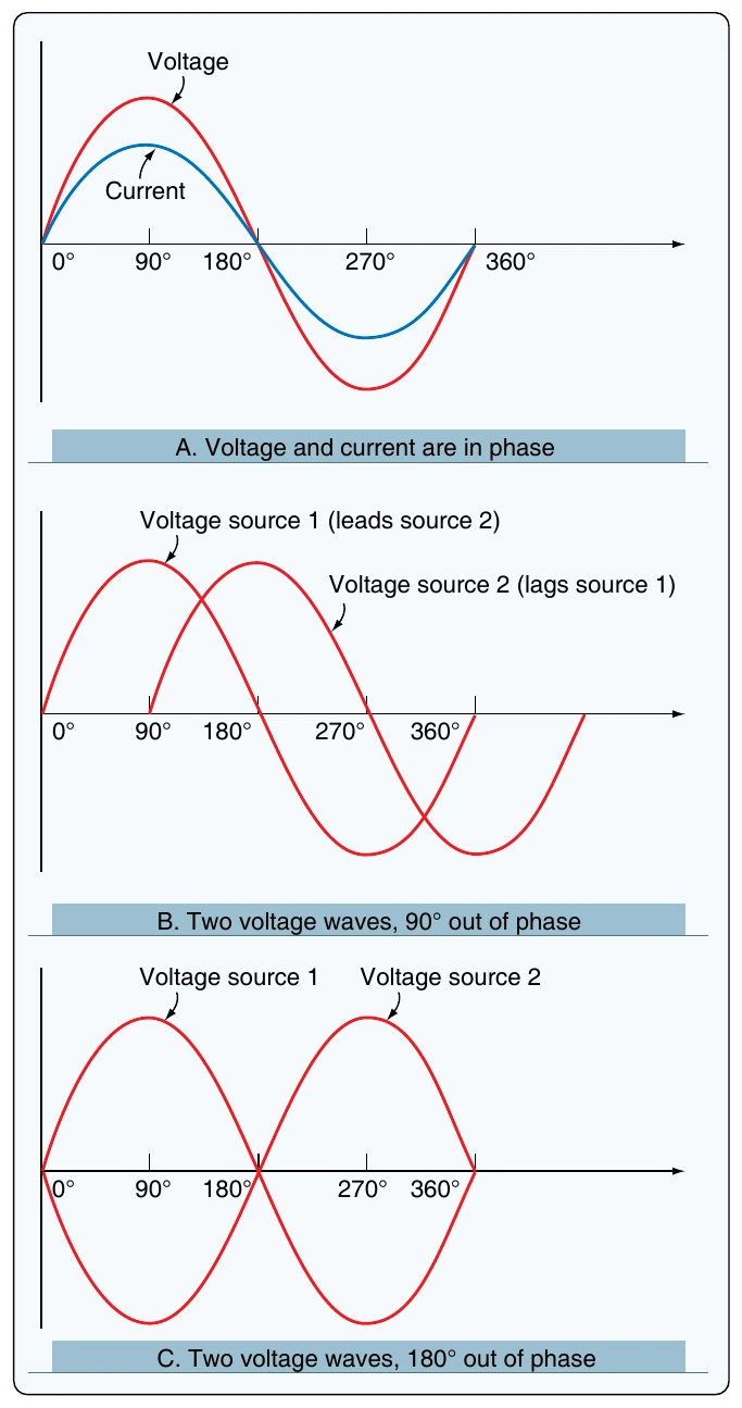
When two waveforms go through their maximum and minimum points at different times, a phase difference exists between the two. In this case, the two waveforms are said to be out of phase with each other. The terms lead and lag are often used to describe the phase difference between waveforms. The waveform that reaches its maximum or minimum value first is said to lead the other waveform. Figure 9-16B shows this relationship. On the other hand, the second waveform is said to be lagging the first source. When a waveform is said to be leading or lagging, the difference in degrees is usually stated. If the two waveforms differ by 360°, they are said to be in phase with each other. If there is a 180° difference between the two signals, then they are still out of phase even though they are both reaching their minimum and maximum values at the same time. [Figure 9-16C]
Opposition to Current Flow of AC
There are three factors that can create an opposition to the flow of electrons (current) in an AC circuit. Resistance, similar to resistance of DC circuits, is measured in ohms and has a direct influence on AC regardless of frequency. Inductive reactance and capacitive reactance, on the other hand, oppose current flow only in AC circuits, not in DC circuits. Since AC constantly changes direction and intensity, inductors and capacitors may also create an opposition to current flow in AC circuits. It should also be noted that inductive reactance and capacitive reactance may create a phase shift between the voltage and current in an AC circuit. Whenever analyzing an AC circuit, it is very important to consider the resistance, inductive reactance, and the capacitive reactance. All three have an effect on the current of that circuit.
Resistance
As mentioned, resistance creates an opposition to current in an AC circuit similar to the resistance of a DC circuit. The current through a resistive portion of an AC circuit is inversely proportional to the resistance and directly proportional to the voltage applied to that circuit or portion
current is related to both voltage and resistance. It should be noted that resistance in an AC circuit does not create a phase shift between voltage and current.
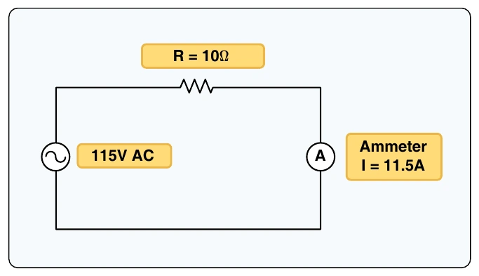
Figure 9-17 shows how a circuit of 10 ohms allows 11.5 amps of current flow through an AC resistive circuit of 115 volts.
Inductive Reactance
When moving a magnet through a coil of wire, a voltage is induced across the coil. If a complete circuit is provided, then a current will also be induced. The amount of induced voltage is directly proportional to the rate of change of the magnetic field with respect to the coil. Conversely, current flowing through a coil of wire produces a magnetic field. When this wire is formed into a coil, it then becomes a basic inductor.
The primary effect of a coil is its property to oppose any change in current through it. This property is called inductance. When current flows through any conductor, a magnetic field starts to expand from the center of the wire. As the lines of magnetic force grow outward through the conductor, they induce an EMF in the conductor itself. The induced voltage is always in the direction opposite to the direction of the applied current flow. The effects of this countering EMF are to oppose the applied current. This effect is only a temporary condition. Once the current reaches a steady value in the conductor, the lines of magnetic force are no longer expanding and the countering EMF is no longer present. Since AC is constantly changing in value, the inductance repeats in a cycle always opposite the applied voltage. It should be noted that the unit of measure for inductance is the henry (H).
The physical factors that affect inductance are:
- Number of turns—doubling the number of turns in a coil produces a field twice as strong if the same current is used. As a general rule, the inductance varies with the square of the number of turns.
- Cross-sectional area of the coil—the inductance of a coil increases directly as the cross-sectional area of the core increases. Doubling the radius of a coil increases the inductance by a factor of four.
- Length of a coil—doubling the length of a coil, while keeping the same number of turns, reduces inductance by one-half.
- Core material around which the coil is formed—
coils are wound on either magnetic or nonmagnetic materials. Some nonmagnetic materials include air, copper, plastic, and glass. Magnetic materials include nickel, iron, steel, and cobalt, which have a permeability that provides a better path for the magnetic lines of force and permit a stronger magnetic field.
Since AC is in a constant state of change, the magnetic fields within an inductor are also continuously changing and create an inducted voltage/current. This induced voltage opposes the applied voltage and is known as the counter EMF. This opposition is called inductive reactance, symbolized by XL, and is measured in ohms. This characteristic of the inductor may also create a phase shift between voltage and current of the circuit. The phase shift created by inductive reactance always causes voltage to lead current. That is, the voltage of an inductive circuit reaches its peak values before the current reaches peak values. Additional discussions related to phase shift are presented later in this chapter.
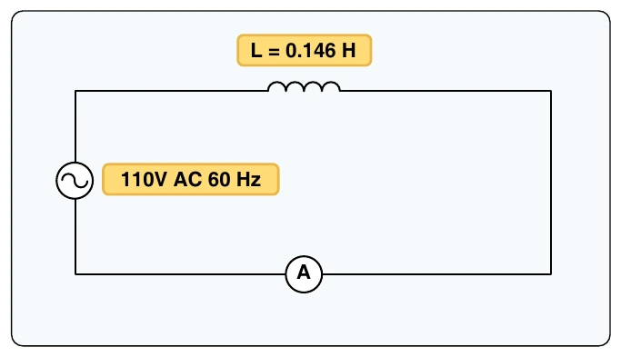
Inductance is the property of a circuit to oppose any change in current and is measured in henries. Inductive reactance is a measure of how much the countering EMF in the circuit opposes the applied current. The inductive reactance of a component is directly proportional to the inductance of the component and the applied frequency to the circuit. By increasing either the inductance or applied frequency, the inductive reactance likewise increases and presents more opposition to current in the circuit. This relationship is given