
Chapter 10
Inspection Concepts & Techniques
Ultrasonic Instruments
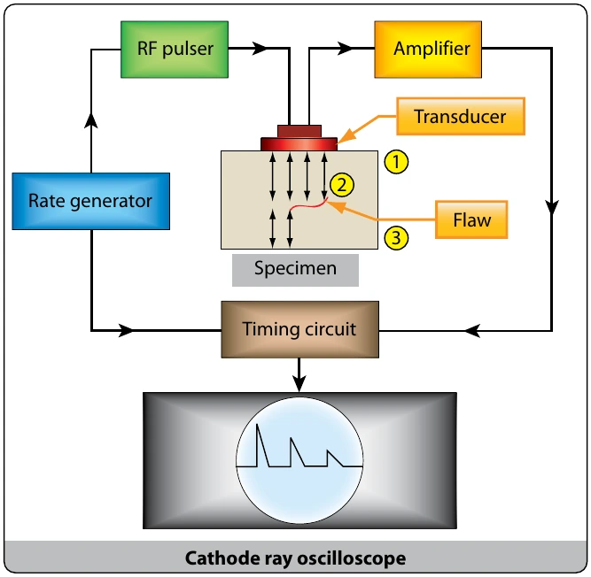
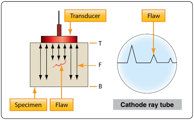
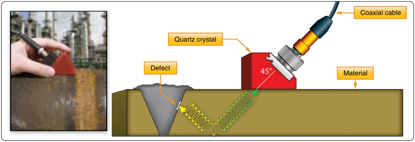
A portable, battery-powered ultrasonic instrument is used for field inspection of airplane structure. The instrument generates an ultrasonic pulse, detects and amplifies the returning echo, and displays the detected signal on a CRT or similar display. Piezoelectric transducers produce longitudinal or shear waves, the most commonly used waveforms for aircraft structural inspection.
Reference Standards
Reference standards are used to calibrate the ultrasonic instrument. Reference standards serve two purposes: to provide an ultrasonic response pattern that is related to the part being inspected and to establish the required inspection sensitivity. To obtain a representative response pattern, the reference standard configuration is the same as that of the test structure or is a configuration that provides an ultrasonic response pattern representative of the test structure. The reference standard contains a simulated defect (notch) that is positioned to provide a calibration signal representative of the expected defect. The notch size is chosen to establish inspection sensitivity (response to the expected defect size). The inspection procedure gives a detailed description of the required reference standard.
Couplants
Inspection with ultrasonics is limited to the part in contact with the transducer. A layer of couplant is required to couple the transducer to the test piece, because ultrasonic energy does not travel through air. Some typical couplants used are water, glycerin, motor oils, and grease.
Inspection of Bonded Structures
Ultrasonic inspection is finding increasing application in aircraft bonded construction and repair. Many configurations and types of bonded structures are in use in aircraft. All of these variations complicate the application of ultrasonic inspections. An inspection method that works well on one part or one area of the part may not be applicable for different parts or areas of the same part. Some of the variables in the types of bonded structures are as follows:
- Top skin material is made from different materials and thickness
- Different types and thickness of adhesives are used in bonded structures
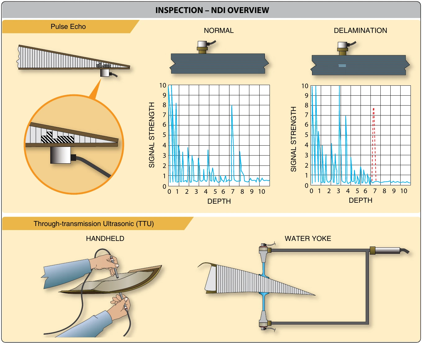
and thickness, doublers (material and thickness), closure member attachments, foam adhesive, steps in skins, internal ribs, and laminates (number of layers, layer thickness, and layer material)
- The top only or top and bottom skin of a bonded structure may be accessible
Types of Defects
Defects can be separated into five general types to represent the various areas of bonded and laminate structures as follows:
- Type I—disbonds or voids in an outer skin-to-adhesive interface.
It is necessary that the frequency of the ultrasonic
- Type II—disbonds or voids at the adhesive-to-core