
Chapter 12
Fundamentals of Electricity & Electronics
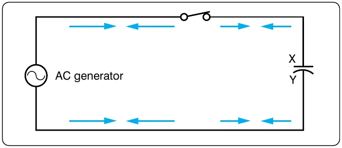
The primary aspect of the operation of a coil is its property to oppose any change in current through it. This property is called inductance. When current flows through any conductor, a magnetic field starts to expand from the center of the wire. As the lines of magnetic force grow outward through the conductor, they induce an emf in the conductor itself. The induced voltage is always in the direction opposite to the direction of the current flow. The effects of this countering emf are to oppose the immediate establishment of the maximum current. This effect is only a temporary condition. Once the current reaches a steady value in the conductor, the lines of magnetic force no longer expand and the countering emf is no longer present.
At the starting instant, the countering emf nearly equals the applied voltage, resulting in a small current flow. However, as the lines of force move outward, the number of lines cutting the conductor per second becomes progressively smaller, resulting in a diminished counter emf. Eventually, the counter emf drops to zero and the only voltage in the circuit is the applied voltage and the current is at its maximum value.
The RL Time Constant
Because the inductors basic action is to oppose a change in its current, it then follows that the current cannot change instantaneously in the inductor. A certain time is required for the current to make a change from one value to another. The rate at which the current changes is determined by a time constant represented by the Greek letter. The time constant for the RL circuit is:
In a series RL circuit, the current increases to 63 percent of its full value in 1 time constant after the circuit is closed. This buildup is similar to the buildup of voltage in a capacitor when charging an RC circuit. Both follow an exponential curve and reach 99 percent value after the 5th time constant. [Figure 12-126]
Physical Parameters
Some of the physical factors that affect inductance are:
- The number of turns: Doubling the number of turns in a coil produces a field twice as strong if the same current is used. As a general rule, the inductance varies as the square of the number of turns.
- The cross-sectional area of the coil: The inductance of a coil increases directly as the cross-sectional area of the core increases. Doubling the radius of a coil increases the inductance by a factor of four.
- The length of a coil: Doubling the length of a coil, while keeping the same number of turns, halves the value of inductance.
- The core material around which the coil is formed: Coils are wound on either magnetic or nonmagnetic materials. Some nonmagnetic materials include air, copper, plastic, and glass. Magnetic materials include nickel, iron, steel, or cobalt, which have a permeability that provides a better path for the magnetic lines of force and permit a stronger magnetic field.
Self-Inductance
The characteristic of self-inductance was summarized by German physicist Heinrich Lenz in 1833, and gives the direction of the induced emf resulting from electromagnetic induction. This is commonly known as Lenz’s Law, which states: The emf induced in an electric circuit always acts in such a direction that the current it drives around a closed circuit produces a magnetic field, which opposes the change in magnetic flux.
Self-inductance is the generation of a voltage in an electric circuit by a changing current in the same circuit. Even a straight piece of wire has some degree of inductance because current in a conductor produces a magnetic field. When the current in a conductor changes direction, there is a corresponding change in the polarity of the magnetic field around the conductor. Therefore, a changing current produces a changing magnetic field around the wire. To further intensify the magnetic field, the wire can be rolled into a coil, which is called an inductor. The changing magnetic field around the inductor induces a voltage across the coil. This induced emf is called self-inductance and tends to oppose any change in current within the circuit. This property is usually called inductance and symbolized with the letter L.
Types of Inductors
Inductors used in radios can range from a straight wire at UHF to large chokes and transformers used for filtering the ripple from the output of power supplies and in audio amplifiers. Figure 12-127 shows the schematic symbols for common inductors. Values of inductors range from nano-henries to tens of henries.
Inductors are classified by the type of core and the method of Cores made of dielectric material like ceramics, wood, and paper provide small amounts of stored energy while cores made of ferrite substances have a much higher degree of stored energy. The core material is usually the most important aspect of the inductors construction. The conductors typically used in the construction of an inductor offer little resistance to the flow of current. However, with the introduction of a core, resistance is introduced in the circuit and the current now builds up in the windings until the resistance of the core is overcome. This buildup is stored as magnetic energy in the core. Depending on the core resistance, the buildup soon reaches a point of magnetic saturation, and it can be released when necessary. The most common core materials are: air, solid ferrite, powdered ferrite, steel, toroid, and ferrite toroid.
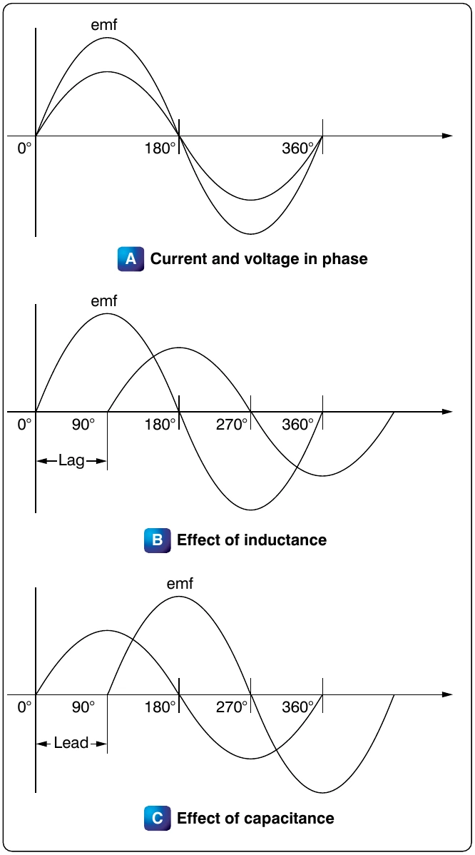
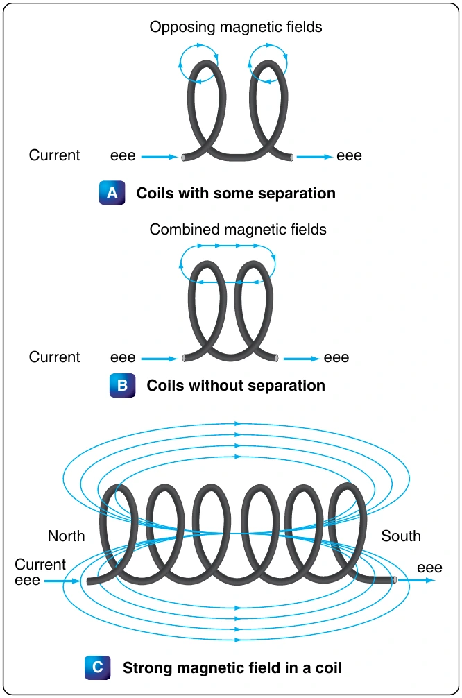
The henry is the basic unit of inductance and is symbolized with the letter H. An electric circuit has an inductance of one henry when current changing at the rate of one ampere per second induces a voltage of one volt into the circuit. In many practical applications, millihenries (mH) and microhenries (μH) are more common units. The typical symbol for an inductor is shown in Figure 12-127.