
Chapter 12
Fundamentals of Electricity & Electronics
If we connect two inductors in series, the same current flows through both inductors and, therefore, both are subject to the same rate of change of current. [Figure 12-128] When inductors are connected in series, the total inductance LT, is the sum of the individual inductors. The general equation for n number of inductors in series is:
Inductors in Parallel
When two inductors are connected in parallel, each must have the same potential difference between the terminals. [Figure 12-129] When inductors are connected in parallel, the total inductance is less than the smallest inductance. The general equation for n number of inductors in parallel is:
1
1 1 +... +
A simple example would be:
Inductive Reactance
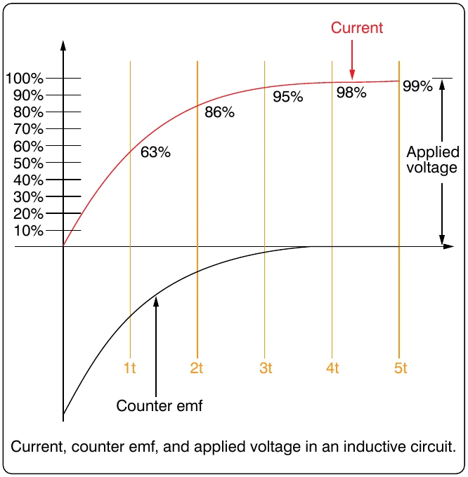
Alternating current is in a constant state of change; the effects of the magnetic fields are a continuously inducted voltage opposition to the current in the circuit. This opposition is called inductive reactance, symbolized by XL, and is measured in ohms just as resistance is measured. Inductance is the property of a circuit to oppose any change in current and is measured in henries. Inductive reactance is a measure of how much the countering emf in the circuit opposes current variations.
The inductive reactance of a component is directly proportional to the inductance of the component and the applied frequency to the circuit. By increasing either the inductance or applied frequency, the inductive reactance likewise increases and presents more opposition to current in the circuit. This relationship is given as:
In Figure 12-130, an AC series circuit is shown in which the inductance is 0.146 henry and the voltage is 110 volts at a frequency of 60 cps. Inductive reactance is determined by the following method.
In any circuit where there is only resistance, the expression for the relationship of voltage and current is given by Ohm’s
circuit, the relationship between voltage and current can be expressed as: