
Chapter 12
Fundamentals of Electricity & Electronics
When trouble develops in a DC motor system, check first to determine the source of the trouble. Replace the motor only when the trouble is due to a defect in the motor itself. In most cases, the failure of a motor to operate is caused by a defect in the external electrical circuit or by mechanical failure in the mechanism driven by the motor.
Check the external electrical circuit for loose or dirty connections and for improper connection of wiring. Look for open circuits, grounds, and shorts by following the applicable manufacturer’s circuit testing procedure. If the fuse is not blown, failure of the motor to operate is usually due to an open circuit. A blown fuse usually indicates an accidental ground or short circuit. A low battery usually causes the chattering of the relay switch, which controls the motor. When the battery is low, the open circuit voltage of the battery is sufficient to close the relay, but with the heavy current draw of the motor, the voltage drops below the level required to hold the relay closed. When the relay opens, the voltage in the battery increases enough to close the relay again. This cycle repeats and causes chattering, which is very harmful to the relay switch due to the heavy current causing an arc which burns the contacts.
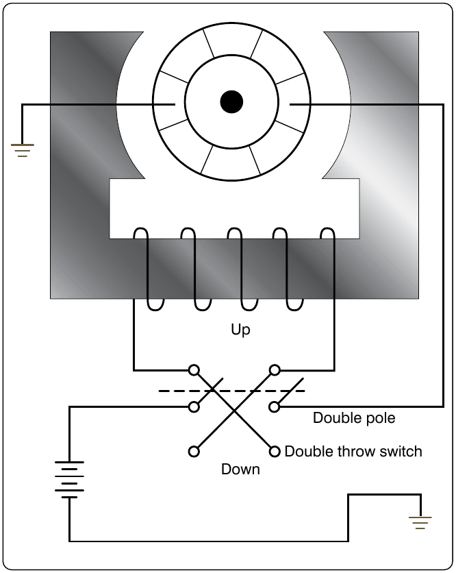
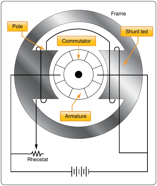
Check the unit driven by the motor for failure of the unit or drive mechanism. If the motor has failed as a result of a failure in the driven unit, the fault must be corrected before installing a new motor. If it has been determined that the fault is in the motor itself (by checking for correct voltage at the motor terminals and for failure of the driven unit), inspect the commutator and brushes. A dirty commutator or defective or binding brushes may result in poor contact between brushes and commutator. Clean the commutator, brushes, and brush holders with a cloth moistened with the recommended cleaning solvent. If brushes are damaged or worn to the specified minimum length, install new brushes in accordance with the applicable manufacturer’s instructions covering the motor. If the motor still fails to operate, replace it with a serviceable motor.
AC Motors
Because of their advantages, many types of aircraft motors are designed to operate on alternating current. In general, AC motors are less expensive than comparable DC motors. In many instances, AC motors do not use brushes and commutators so sparking at the brushes is avoided. AC motors are reliable and require little maintenance. They are also well suited for constant speed applications and certain types are manufactured that have, within limits, variable speed characteristics. Alternating current motors are designed to operate on polyphase or single-phase lines and at several voltage ratings.
The speed of rotation of an AC motor depends upon the number of poles and the frequency of the electrical source of power:
Since airplane electrical systems typically operate at 400 cycles, an electric motor at this frequency operates at about seven times the speed of a 60-cycle commercial motor with the same number of poles. Because of this high speed of rotation, 400-cycle AC motors are suitable for operating small, high-speed rotors, through reduction gears, in lifting and moving heavy loads, such as the wing flaps, the retractable landing gear, and the starting of engines. The 400-cycle induction type motor operates at speeds ranging from 6,000 rpm to 24,000 rpm. Alternating current motors are rated in horsepower output, operating voltage, full load current, speed, number of phases, and frequency. Whether the motors operate continuously or intermittently (for short intervals) is also considered in the rating.
Types of AC Motors
There are two general types of AC motors used in aircraft systems: induction motors and synchronous motors. Either type may be single-phase, two-phase, or three-phase. Three-phase induction motors are used where large amounts of power are required. They operate such devices as starters, flaps, landing gears, and hydraulic pumps. Single-phase induction motors are used to operate devices such as surface locks, intercooler shutters, and oil shutoff valves in which the power requirement is low. Three-phase synchronous motors operate at constant synchronous speeds and are commonly used to operate flux gate compasses and propeller synchronizer systems. Single-phase synchronous motors are common sources of power to operate electric clocks and other small, precision equipment. They require some auxiliary method to bring them up to
Three-Phase Induction Motor
The three-phase AC induction motor is also called a squirrel cage motor. Both single-phase and three-phase motors operate on the principle of a rotating magnetic field. A horseshoe magnet held over a compass needle is a simple illustration of the principle of the rotating field. The needle takes a position parallel to the magnetic flux passing between the two poles of the magnet. If the magnet is rotated, the compass needle follows. A rotating magnetic field can be produced by a two-or three-phase current flowing through two or more groups of coils wound on inwardly projecting poles of an iron frame. The coils on each group of poles are wound alternately in opposite directions to produce opposite polarity, and each group is connected to a separate phase of voltage. The operating principle depends on a revolving, or rotating, magnetic field to produce torque. The key to understanding the induction motor is a thorough understanding of the rotating magnetic field.
Rotating Magnetic Field
The field structure shown in Figure 12-307A has poles whose windings are energized by three AC voltages: a, b, and c. These voltages have equal magnitude but differ in phase. [Figure 12-307B] At the instant of time shown as 0, the resultant magnetic field produced by the application of the three voltages has its greatest intensity in a direction extending from pole 1 to pole 4. Under this condition, pole 1 can be considered as a North pole and pole 4 as a South pole. At the instant of time shown as 1, the resultant magnetic field has its greatest intensity in the direction extending from pole 2 to pole 5. In this case, pole 2 can be considered as a North pole and pole 5 as a South pole. Thus, between instant 0 and instant 1, the magnetic field has rotated clockwise. At instant 2, the resultant magnetic field has its greatest intensity in the direction from pole 3 to pole 6, and the resultant magnetic field has continued to rotate clockwise. At instant 3, poles 4 and 1 can be considered as North and South poles, respectively, and the field has rotated still farther. At later instants of time, the resultant magnetic field rotates to other positions while traveling in a clockwise direction, a single revolution of the field occurring in one cycle. If the exciting voltages have a frequency of 60 cps, the magnetic field makes 60 revolutions per second, or 3,600 rpm. This speed is known as the synchronous speed of the rotating field.
Construction of Induction Motor
The stationary portion of an induction motor is called a stator, and the rotating member is called a rotor. Instead of salient poles in the stator, as shown in Figure 12-307A, distributed windings are used. These windings are placed in slots around the periphery of the stator. It is usually impossible to determine the number of poles in an induction motor by visual inspection, but the information can be obtained from the nameplate of the motor. The nameplate usually gives the number of poles and the speed at which the motor is designed to run. This rated, or nonsynchronous, speed is slightly less than the synchronous speed. To determine the number of poles per phase on the motor, divide 120 times the frequency by the rated speed. Written as an equation, it is: