
Chapter 12
Fundamentals of Electricity & Electronics
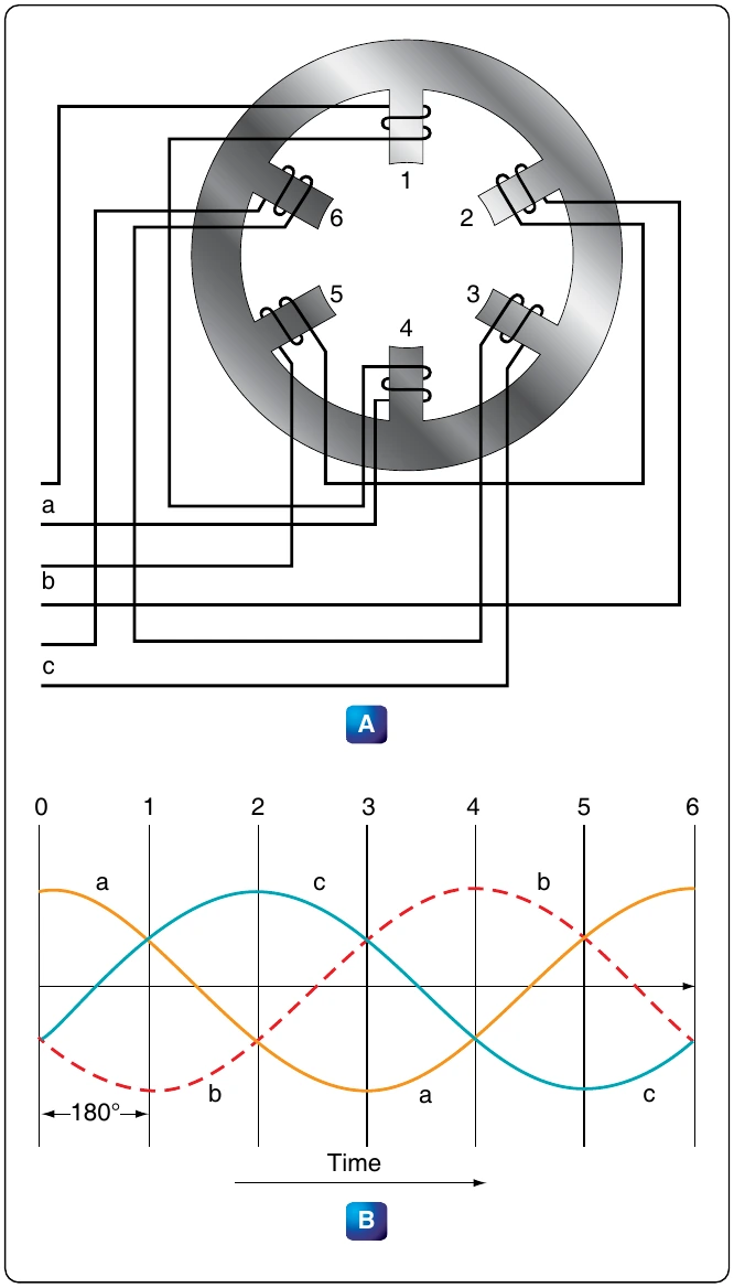
Where: P is the number of poles per phase f is the frequency in cps N is the rated speed in rpm, and 120 is a constant
The result is nearly equal to the number of poles per phase. For example, consider a 60-cycle, three-phase motor with a rated speed of 1,750 rpm. In this case:
Therefore, the motor has four poles per phase. If the number of poles per phase is given on the nameplate, the synchronous speed can be determined by dividing 120 times the frequency by the number of poles per phase. In the example used above,
The rotor of an induction motor consists of an iron core having longitudinal slots around its circumference in which heavy copper or aluminum bars are embedded. These bars are welded to a heavy ring of high conductivity on either end. The composite structure is sometimes called a squirrel cage, and motors containing such a rotor are called squirrel cage induction motors. [Figure 12-308]
Induction Motor Slip
When the rotor of an induction motor is subjected to the revolving magnetic field produced by the stator windings, a voltage is induced in the longitudinal bars. The induced voltage causes a current to flow through the bars. This current, in turn, produces its own magnetic field, which combines with the revolving field so that the rotor assumes a position in which the induced voltage is minimized. As a result, the rotor revolves at very nearly the synchronous speed of the stator field, the difference in speed being just sufficient enough to induce the proper amount of current in the rotor to overcome the mechanical and electrical losses in the rotor. If the rotor were to turn at the same speed as the rotating field, the rotor conductors would not be cut by any magnetic lines of force, no EMF would be induced in them, no current could flow, and there would be no torque. The rotor would then slow down. For this reason, there must always be a difference in speed between the rotor and the rotating field. This difference in speed is called slip and is expressed as a percentage of the synchronous speed. For example, if the rotor turns at 1,750 rpm
Single-Phase Induction Motor
The previous discussion has applied only to polyphase motors. A single-phase motor has only one stator winding. This winding generates a field, which merely pulsates, instead of rotating. When the rotor is stationary, the expanding and collapsing stator field induces currents in the rotor. These currents generate a rotor field opposite in polarity to that of the stator. The opposition of the field exerts a turning force on the upper and lower parts of the rotor trying to turn it 180° from its position. Since these forces are exerted through the center of the rotor, the turning force is equal in each direction. As a result, the rotor does not turn. If the rotor starts turning, it continues to rotate in the direction in which it started, since the turning force in that direction is aided by the momentum of the rotor.
Shaded Pole Induction Motor
The first effort in the development of a self-starting, single-phase motor was the shaded pole induction motor. [Figure 12-309] This motor has salient poles, a portion of each pole being encircled by a heavy copper ring. The presence of the ring causes the magnetic field through the ringed portion of the pole face to lag appreciably behind that through the other part of the pole face. The net effect is the production of a slight component of rotation of the field, sufficient to cause the rotor to revolve. As the rotor accelerates, the torque increases until the rated speed is obtained. Such motors have low starting torque and find their greatest application in small fan motors where the initial torque required is low.
In Figure 12-309, a diagram of a pole and the rotor is shown. The poles of the shaded pole motor resemble those of a DC motor.
A low resistance, short-circuited coil or copper band is placed across one tip of each small pole from which the motor gets the name of shaded pole. The rotor of this motor is the squirrel cage type. As the current increases in the stator winding, the flux increases. A portion of this flux cuts the low resistance shading coil. This induces a current in the shading coil, and by Lenz’s Law, the current sets up a flux that opposes the flux inducing the current. Hence, most of the flux passes through the unshaded portion of the poles. [Figure 12-310]
When the current in the winding and the main flux reaches a maximum, the rate of change is zero; thus, no emf is induced in the shading coil. A little later, the shading coil current, which causes the induced emf to lag, reaches zero, and there is no opposing flux. Therefore, the main field flux in the shading coil. This current sets up a flux that opposes the decrease of the main field flux in the shaded portion of the pole. The effect is to concentrate the lines of force in the shaded portion of the pole face. In effect, the shading coil retards, in time phase, the portion of the flux passing through the shaded part of the pole. This lag in time phase of the flux in the shaded tip causes the flux to produce the effect of sweeping across the face of the pole, from left to right in the direction of the shaded tip. This behaves like a very weak rotating magnetic field, and sufficient torque is produced to start a small motor. The starting torque of the shaded pole motor is exceedingly weak, and the power factor is low. Consequently, it is built in sizes suitable for driving such devices as small fans.
Split-Phase Motor
There are various types of self-starting motors, known as split-phase motors. Such motors have a starting winding displaced 90 electrical degrees from the main or running winding. In some types, the starting winding has a fairly high resistance, which causes the current in this winding to be out of phase with the current in the running winding. This condition produces, in effect, a rotating field and the rotor revolves. A centrifugal switch disconnects the starting winding automatically after the rotor has attained approximately 25 percent of its rated speed.