
Chapter 6
Aircraft Weight & Balance
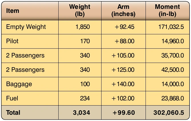
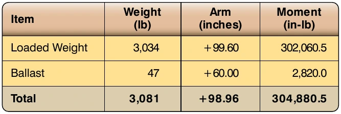
is being placed in the baggage compartment at an arm of 60". The difference between the two is 39", the quantity divided by in the formula.
Viewed as a first-class lever problem, Figure 6-42 shows what this ballast calculation would look like. A ballast weight of 46.68 lb on the left side of the lever multiplied by the arm of 39" (99 minus 60) would equal the aircraft weight of 3,034 lb multiplied by the distance the CG is out of limits, which is 0.6" (99.6 minus 99).
Permanent Ballast
If a repair or alteration causes the aircraft CG to fall outside of its limit, permanent ballast can be installed. Usually, permanent ballast is made of blocks of lead painted red and marked “Permanent Ballast–Do Not Remove.” It should be attached to the structure so that it does not interfere with any control action, and attached rigidly enough that it cannot be dislodged by any flight maneuvers or rough landing. The installation of permanent ballast results in an increase in the aircraft empty weight, and it reduces the useful load.
Three things must be known to determine the amount of ballast needed to bring the CG within limits: the amount the CG is out of limits, the distance between the location of the ballast, and the limit that is affected. If an airplane with an empty weight of 1,876 lb has been altered so its EWCG is +32.2, and CG range for weights up to 2,250 lb is +33.0 to +46.0, permanent ballast must be installed to move the EWCG from +32.2 to +33.0. There is a bulkhead at fuselage station 228 strong enough to support the ballast. To determine the amount of ballast needed, use this formula:
228 33
marked “Permanent Ballast– Do Not Remove.”
Loading Graphs & CG Envelopes
The weight and balance computation system, commonly called the loading graph and CG envelope system, is an excellent and rapid method for determining the CG location for various loading arrangements. This method can be applied to any make and model of aircraft, but is more often seen with small GA aircraft.
Aircraft manufacturers using this method of weight and balance computation prepare graphs like those shown in Figures 6-43 and 6-44 for each make and model aircraft at the time of original certification. The graphs become a permanent part of the aircraft records and are typically found in the AFM/POH. These graphs, used in conjunction with the empty weight and EWCG data found in the weight and balance report, allow the pilot to plot the CG for the loaded aircraft.
The loading graph in Figure 6-43 is used to determine the index number (moment value) of any item or weight that may be involved in loading the aircraft. To use this graph, find the point on the vertical scale that represents the known weight. Project a horizontal line to the point where it intersects the proper diagonal weight line (i.e., pilot, copilot, baggage). Where the horizontal line intersects the diagonal, project a vertical line downward to determine the loaded moment (index number) for the weight being added.
After the moment for each item of weight has been vertical scale of the graph, with a horizontal line projected out from that point. The total moment is plotted on the horizontal scale of the graph, with a vertical line projected up from that point. Where the horizontal and vertical plot lines intersect on the graph is the CG for the loaded aircraft. If the point where the plot lines intersect falls inside the CG envelope, the aircraft CG is within limits. In Figure 6-44, there are two CG envelopes, one for the aircraft in the Normal Category and one for the aircraft in the Utility Category.
The loading graph and CG envelope shown in Figures 6-43 and 6-44 are for an airplane with the following specifications and weight and balance data.
- Number of seats: 4
- Fuel capacity (usable): 38 gal of Avgas
- Oil capacity: 8 qt (included in empty weight)
- Baggage: 120 lb
- Empty weight: 1,400 lb
- EWCG: 38.5"
- Empty weight moment: 53,900 in-lb