
Chapter 9
Fluid Lines & Fittings
One of the latest developments is the Permalite™ fitting. Permalite™ is a tube fitting that is mechanically attached to the tube by axial swaging. Permalite™ works by deforming the fitting into the tube being joined by moving a ring, a component of the Permalite™ fitting, axially along the fitting length using a Permaswage™ Axial swage tool. Typical Permalite™ fittings are shown in Figure 9-26.
Cryofit Fittings
Many transport category aircraft use Cryofit fittings to join hydraulic lines in areas where routine disconnections are not required. Cryofit fittings are standard fittings with a cryogenic sleeve. The sleeve is made of a shape memory alloy, Tinel™.
liquid nitrogen and inserted onto the tube. During a 10 to 15 second warming up period, the fitting contracts to its original size (3 percent smaller), biting down on the tube, forming a permanent seal. Cryofit fittings can only be removed by cutting the tube at the sleeve, though this leaves enough room to replace it with a swaged fitting without replacing the hydraulic line. It is frequently used with titanium tubing. The shape memory technology is also used for end fittings, flared fittings, and flareless fittings. [Figure 9-27] carefully. Remove dents and scratches, and be sure all nuts and sleeves are snugly mated and securely fitted by proper flaring of the tubing. The line assembly should be clean and free of all foreign matter.
Connection & Torque
Never apply compound to the faces of the fitting or the flare, as it destroys the metal-to-metal contact between the fitting and flare, a contact which is necessary to produce the seal. Be sure that the line assembly is properly aligned before tightening the fittings. Do not pull the installation into place with torque on the nut. Correct and incorrect methods of installing flared tube assemblies are illustrated in
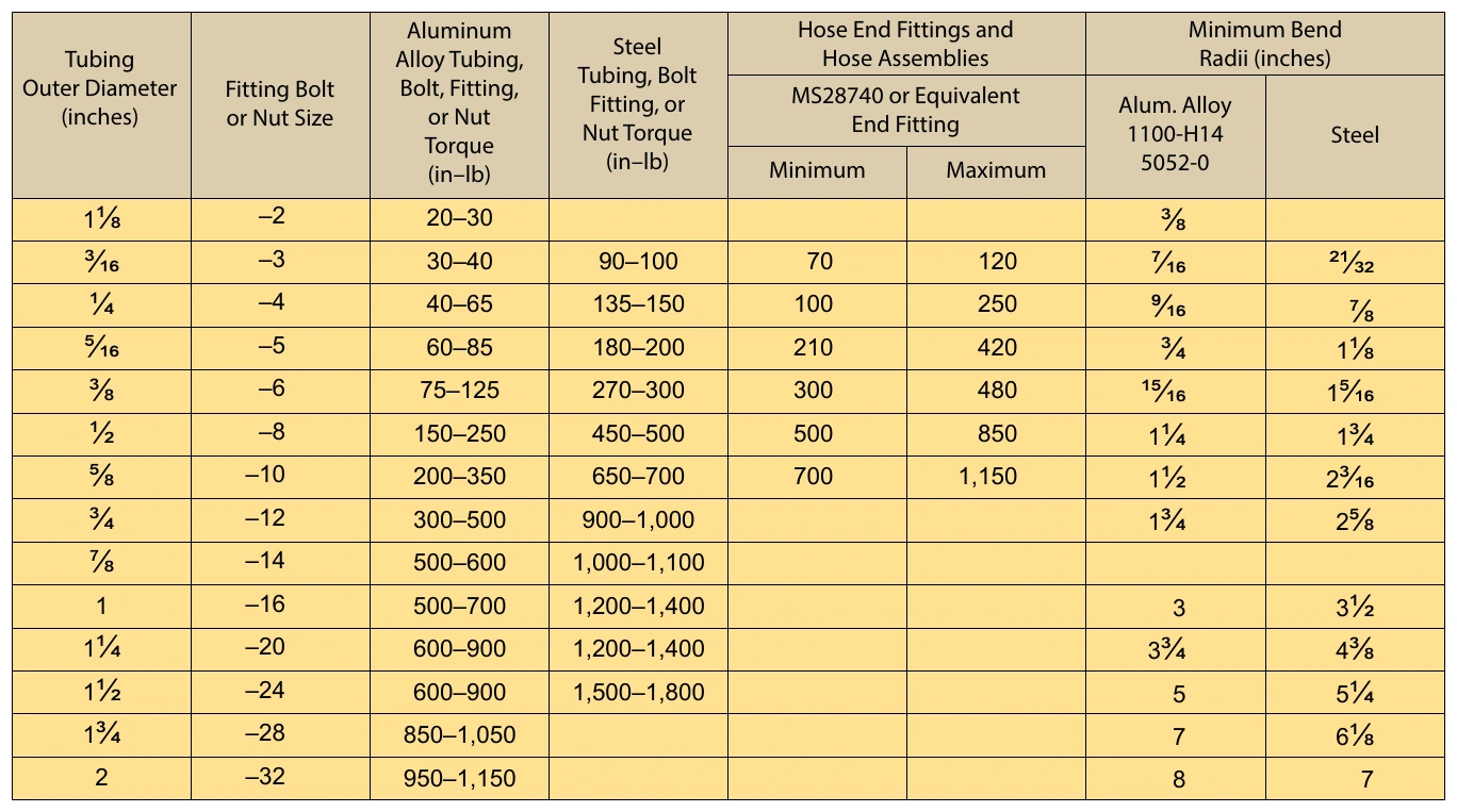
Remember that these torque values are for flared-type fittings only. Always tighten fittings to the correct torque value when installing a tube assembly. Overtightening a fitting may badly of the assembly or to leak under system pressure. The use of torque wrenches and the prescribed torque values prevents overtightening or undertightening. If a tube fitting assembly is tightened properly, it may be removed and retightened many times before reflaring is necessary.
Flareless Tube Installation
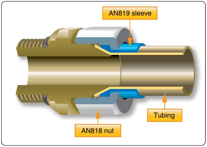
Tighten the nut by hand until an increase in resistance to turning is encountered. Should it be impossible to run the nut down with the fingers, use a wrench, but be alert for the first signs of bottoming. It is important that the final tightening commence at the point where the nut just begins to bottom. Use a wrench and turn the nut one-sixth turn (one flat on a hex nut). Use a wrench on the connector to prevent it from turning while tightening the nut. After the tube assembly is installed, the system should be pressure tested. It is permissible to tighten the nut an additional one-sixth turn (making a total of one-third turn), should a connection leak. If leakage still occurs after tightening the nut a total of one-third turn, remove the assembly and inspect the components for scores, cracks, presence of foreign material, or damage from overtightening. Several aircraft manufacturers include torque values in their maintenance manuals to tighten the flareless fittings.
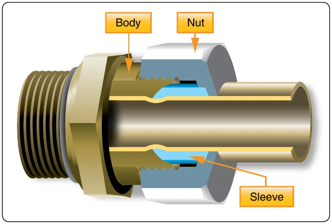
Caution: Never tighten the nut beyond one-third turn (two flats on the hex nut); this is the maximum the fitting may be tightened without the possibility of permanently damaging the sleeve and nut.
Common faults: Flare distorted into nut threads; sleeve cracked; flare cracked or split; flare out of round; inside of flare rough or scratched; and threads of nut or union dirty, damaged, or broken.