
Chapter 9
Fluid Lines & Fittings
Rigid Tubing Inspection & Repair
Minor dents and scratches in tubing may be repaired. Scratches or nicks not deeper than 10 percent of the wall thickness in aluminum alloy tubing, which are not in the heel of a bend, may be repaired by burnishing with hand tools. The damage limits for hard, thin-walled corrosion-resistant steel and titanium tubing are considerably less than for aluminum tubing and might depend on the aircraft manufacturer. Consult the aircraft maintenance manual for damage limits. Replace lines with severe die marks, seams, or splits in the tube. Any crack or deformity in a flare is unacceptable and is cause for rejection. A dent of less than 20 percent of the tube diameter is not objectionable, unless it is in the heel of a bend. To remove dents, draw a bullet of proper size through the tube by means of a length of cable, or push the bullet through a short straight tube by means of a dowel rod. In this case, a bullet is a ball bearing or slug normally made of steel or some other hard metal. In the case of soft aluminum tubing, a hard wood slug or dowel may even be used as a bullet. [Figure 9-29] A severely damaged line should be replaced. However, the line may be repaired by cutting out the damaged section and inserting a tube section of the same size and material. Flare both ends of the undamaged and replacement tube sections and make the connection by using standard unions, sleeves, and tube nuts. Aluminum 6061-T6, corrosion-resistant steel 304-1/8h and Titanium 3AL-2.5V tubing can be repaired by swaged fittings. If the damaged portion is short enough, omit the insert tube and repair by using one repair union. [Figure 9-30] When repairing a damaged line, be very careful to remove all chips and burrs. Any open line that is to be left unattended for a period of time should be sealed, using metal, wood, rubber, gs.
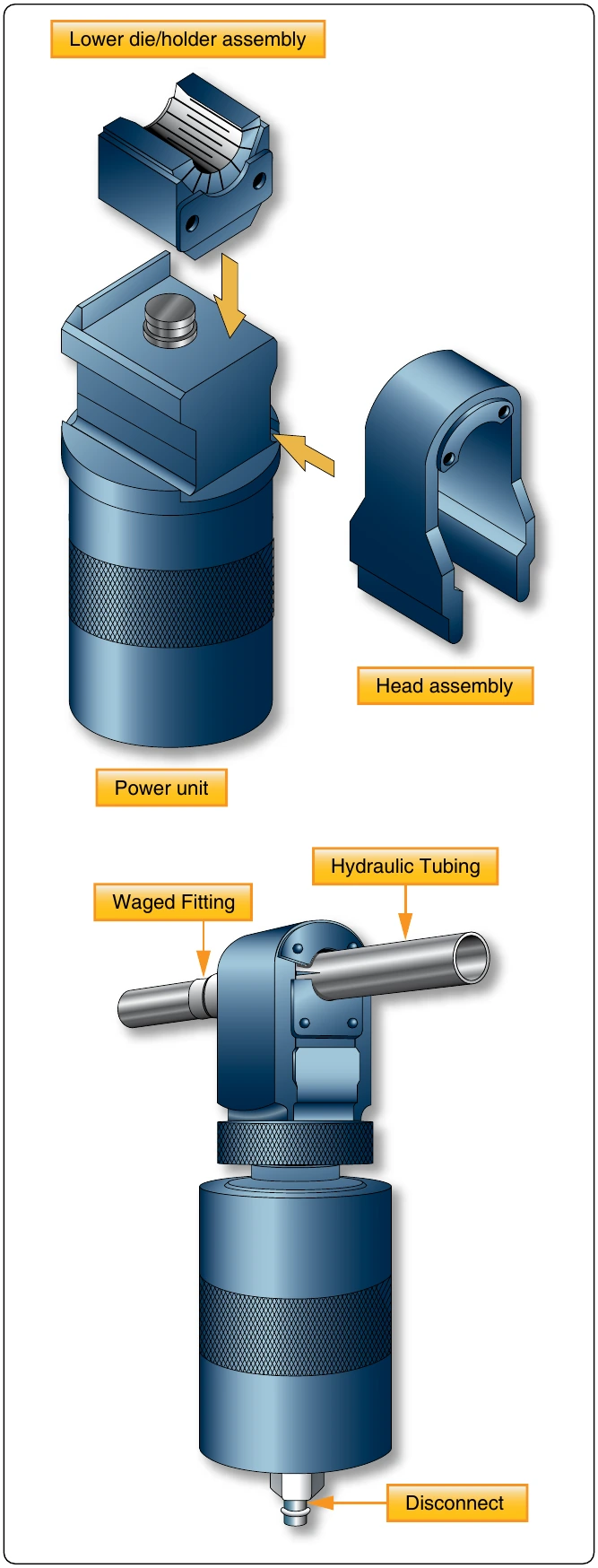
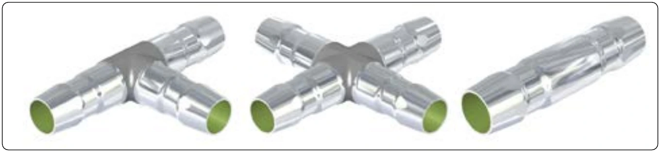
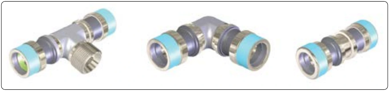
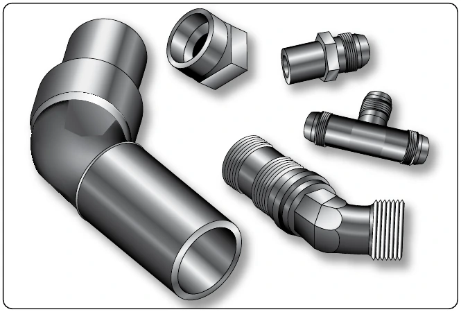
or plastic plugs or caps.
When repairing a low-pressure line using a flexible fluid connection assembly, position the hose clamps carefully to prevent overhang of the clamp bands or chafing of the tightening screws on adjacent parts. If chafing can occur, the hose clamps should be repositioned on the hose. Figure 9-31 illustrates the design of a flexible fluid connection assembly and gives the maximum allowable angular and dimensional offset.
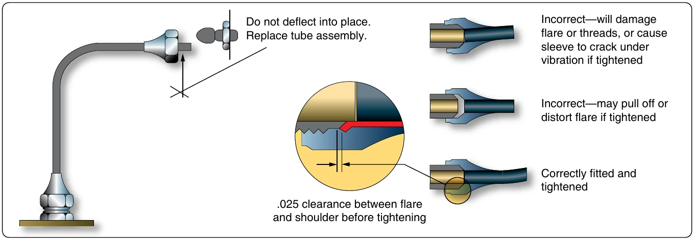
When replacing rigid tubing, ensure that the layout of the new line is the same as that of the line being replaced. Remove the damaged or worn assembly, taking care not to further damage or distort it, and use it as a forming template for the new part. If the old length of tubing cannot be used as a pattern, make a wire template, bending the pattern by hand as required for the new assembly. Then bend the tubing to match the wire pattern. Never select a path that does not require bends in the tubing. A tube cannot be cut or flared accurately enough so that it can be installed without bending and still be free from mechanical strain. Bends are also necessary to permit the tubing to expand or contract under temperature changes and to absorb vibration. If the tube is small (under 1⁄4") and can be hand formed, casual bends may be made to allow for this. If the tube must be machine formed, definite bends must be made to avoid a straight assembly. Start all bends a reasonable distance from the fittings because the sleeves and nuts must be slipped back during the fabrication of flares and during inspections. In all cases, the new tube assembly should be so formed prior to installation that it is not necessary to pull or deflect the assembly into alignment by means of the coupling nuts.
Flexible Hose Fluid Lines
Flexible hose is used in aircraft fluid systems to connect moving parts with stationary parts in locations subject to vibration or where a great amount of flexibility is needed. It can also serve as a connector in metal tubing systems.
Hose Materials & Construction
Pure rubber is never used in the construction of flexible fluid lines. To meet the requirements of strength, durability, and workability, among other factors, synthetics are used in place of pure rubber. Synthetic materials most commonly used in the manufacture of flexible hose are Buna-N, neoprene, butyl, ethylene propylene diene rubber (EPDM) and Teflon™. While Teflon™ is in a category of its own, the others are synthetic rubber.
Buna-N
Buna-N is a synthetic rubber compound that has excellent resistance to petroleum products. Do not confuse with Buna-S. Do not use for phosphate ester base hydraulic fluid (Skydrol™).
Neoprene
Neoprene is a synthetic rubber compound that has an acetylene base. Its resistance to petroleum products is not as good as Buna-N, but it has better abrasive resistance. Do not use for phosphate ester base hydraulic fluid (Skydrol™).
Butyl
Butyl is a synthetic rubber compound made from petroleum raw materials. It is an excellent material to use with phosphate ester base hydraulic fluid (Skydrol™). Do not use with petroleum products.